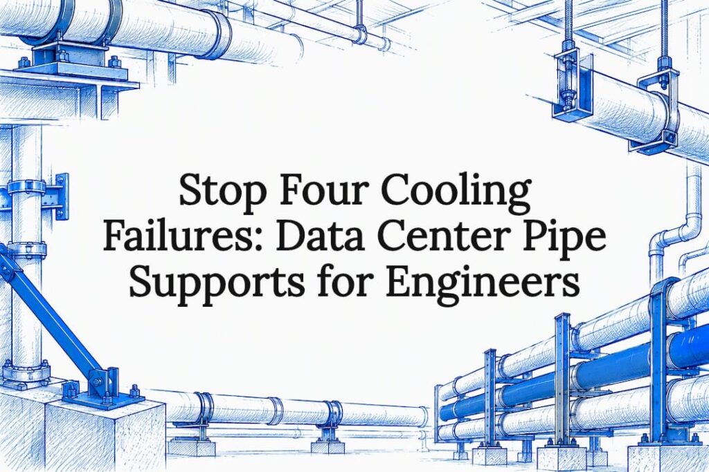
Specify engineered, pre-insulated, seismic-rated pipe supports sized by PE-stamped calculations. This single decision prevents the four failure modes that take cooling systems down: thermal bridging, condensation, vibration fatigue, and earthquake-induced pipe displacement. Supports should be braced per ASCE 7-22 and anchored with ICC-ES evaluated hardware sized to ACI 318.
TL;DR:
- Support spacing should account for full fluid weight and seismic displacement, with minimum clearance of four times the maximum seismic movement between pipes.
- Pre-insulated supports are essential in chilled water and humid environments to prevent condensation and corrosion by maintaining continuous vapor barriers.
- Seismic bracing for piping in Risk Category IV data centers must be sized by a PE-stamped calculation with an importance factor of 1.5, increasing design forces by about 50 percent.
- Use supports with adjustable features and verify insulation and seismic documentation in support submittals to reduce field rework and inspection failures.
- Engineers should specify detailed load ratings, seismic requirements, and current evaluation reports before procurement to ensure support reliability and compliance.
Table of Contents
- Types of Pipe Supports and Material Choices for Data Centers
- Thermal Bridging, Condensation Risk, and Pre-Insulated Supports
- Seismic Bracing and Anchorage: ASCE 7-22 Implications for Data Center Piping
- Span, Spacing, and Load Calculations for Support Placement
- Vibration, Thermal Movement, and Flexible Connectors
- Specification and Installation Checklist for Engineers and Facility Managers
- Guoqiang Capabilities and Product Fit for Data Center Pipe Supports
- What Most Specifications Get Wrong About Pipe Supports
- How to Contact GQ for Product Data, Quotes, and PE-Stamped Engineering
- FAQ
- Sources
- Authoritative Standards and Technical Resources
Types of Pipe Supports and Material Choices for Data Centers
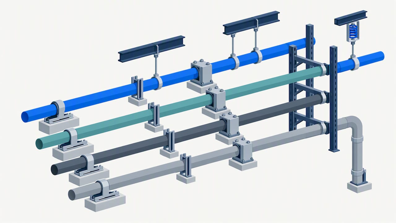
Chilled water, condenser water, generator fuel, and drain lines each demand different hardware. Pipe shoes carry axial load while allowing slide movement during thermal expansion. Guides keep pipe centered as it moves. Anchors fix a point rigidly to resist both gravity and seismic load. Hangers suspend lines from overhead structure, while distributed brackets split load across multiple pipe runs on racks or raised-floor pedestals. Variable spring supports absorb movement on lines that shift vertically as temperature swings.
Material choice follows service conditions. Stainless steel resists the corrosion common in condenser water loops and coastal or humid climates. Carbon steel costs less but needs coating or insulation to avoid rust at support contact points. CPVC and other thermoplastics work for low-pressure drain or makeup water lines, but ASHRAE’s piping guidance notes that plastics expand more per degree of temperature change and tolerate shorter spans between supports than metal pipe. Some jurisdictions restrict plastic piping in plenum spaces over fire and toxicity concerns.
Pre-insulated supports earn their premium on any line where surface temperature drops near room dew point:
- Chilled water supply and return lines running below ambient temperature
- Condenser water loops in humid climates
- Any run passing through a raised-floor plenum shared with airflow
Thermal Bridging, Condensation Risk, and Pre-Insulated Supports
A bare metal support clamped directly to insulated pipe creates a thermal bridge: a path for heat to cross the insulation barrier at exactly the point where the pipe is mechanically fixed. On a chilled water line, that bridge point drops below the dew point of the surrounding air, and moisture condenses directly onto steel, clamps, and anchor bolts. Left unaddressed, that moisture corrodes hardware, drips onto equipment below, and quietly bleeds cooling capacity at every support location across a server hall.
Pre-insulated supports solve this by molding high-density insulation, typically polyurethane foam or cellular glass, around the pipe at the support interface, maintaining a continuous vapor barrier instead of breaking it. Field installation needs attention to three details:
- Avoid over-tightening clamps, which crushes insulation and reopens the thermal path
- Seal vapor-barrier jacketing with compatible mastic or tape at every support penetration
- Confirm slide plate compatibility so the insulated support can still move freely under thermal expansion
Pro Tip: Specify insulation thickness and vapor barrier continuity in the support schedule itself, not just in the pipe insulation spec. A support that is an afterthought on the drawing is usually the one that sweats in the field.
Seismic Bracing and Anchorage: ASCE 7-22 Implications for Data Center Piping
Most data centers qualify as Risk Category IV facilities, and that classification changes the math. Under ASCE 7-22 Chapter 13, nonstructural components in Risk Category IV buildings carry an importance factor of Ip = 1.5, which raises calculated seismic design forces on piping, supports, and anchors by roughly 50% compared with standard occupancies.
Seismic design forces apply to piping in Risk Category IV facilities under Ip = 1.5 with a significant increase, per ASCE 7-22 bracing requirements. That multiplier changes anchor diameter, embedment depth, and brace spacing, so a design copied from a lower-risk building will under-brace a data center.
Practical steps for engineers specifying bracing:
- Confirm occupancy classification and Ip value before sizing any brace or anchor.
- Brace steel piping at or above about 1 inch NPS in Ip = 1.5 systems, and at or above pipe sizes larger than typical smaller diameters in standard systems, per the same seismic guidance.
- Select anchors with current ICC-ES evaluation reports and size embedment per ACI 318 anchor design provisions.
- Document calculations with a PE stamp referencing the project’s site seismic parameters before submitting for permit.
Inspection failures cluster around two issues: anchors without a valid ICC-ES ESR for the application, and missing torque verification logs. Both are avoidable with upfront documentation rather than field improvisation.
Span, Spacing, and Load Calculations for Support Placement
Support spacing starts with a span-to-diameter relationship, then gets refined once pipe contents, attachments, and seismic displacement are factored in. UpCodes’ summary of support and attachment rules provides allowable span tables by diameter for both rigid and flexible piping systems, with a practical rigid-versus-flexible distinction based on the natural period of the support assembly, roughly a 0.06-second threshold separating rigid behavior from flexible response under seismic load.
Three factors push spacing tighter than the basic table value:
- Fluid-filled weight: a water-filled line weighs far more than empty pipe, and spacing must account for full operating weight, not dry weight
- Attachments: valves, flex connectors, and instrumentation add concentrated loads that need their own support points nearby
- Seismic displacement clearance: parallel pipes need enough separation to avoid contact as they swing independently during an earthquake
The same UpCodes guidance sets minimum separation between parallel pipes at four times the calculated maximum displacement from seismic force, not less than a few inches, and a minimum clearance to rigid structural elements of a few inches, as per standard seismic pipe bracing guidance. Spreaders maintain that clearance at crossing points and tray transitions where pipes run close together by design.
Vibration, Thermal Movement, and Flexible Connectors
Pumps and chillers transmit vibration into piping, and unmanaged vibration fatigues welds, loosens anchors, and eventually cracks pipe at support points. Resilient mounts and damping clamps absorb that energy at the support interface rather than letting it travel down the line, and they belong near rotating equipment connections and anywhere a pipe run crosses a structural isolation joint.
Thermal movement needs its own detailing. Nested U-loops and integrated bellows give piping room to expand and contract without overstressing fittings, while metallic expansion joints and flex connectors handle movement in tighter mechanical rooms. Each flex connector needs bracing on both sides to keep seismic force from concentrating at the flexible joint itself, which is often the weakest point in the run.
- Specify adjustable supports and slide plates wherever final pipe elevation depends on field conditions
- Confirm insulation jacketing still seals properly around any slide plate or expansion joint after adjustment
Pro Tip: Lock in adjustable support interfaces early in design. Field teams can set final elevations on site without refabricating a single bracket, which saves schedule time during commissioning.
Specification and Installation Checklist for Engineers and Facility Managers
A support RFQ should leave no room for substitution on the items that drive reliability.
- Require a full support schedule by line, noting type, material, insulation continuity, and load rating for each point.
- State seismic requirements explicitly, including Risk Category, Ip value, and site seismic parameters, rather than leaving bracing to a generic vendor kit.
- Require adjustability where final elevation is uncertain, and specify finish (stainless, galvanized, coated) matched to the service environment.
- Request PE-stamped calculations and current ICC-ES ESRs for every anchor type before ordering.
- Require torque verification logs during installation, and schedule field inspection against the stamped drawings.
Maintenance after commissioning should check torque values at a sample of anchors, inspect insulation jacketing for gaps or moisture staining, and confirm expansion joints still have their full rated range of movement.
Guoqiang Capabilities and Product Fit for Data Center Pipe Supports
Our support lines map directly onto the needs above. GQ-FL series flexible supports handle thermal expansion and vibration damping on chilled water and condenser runs. GQ-D Series Distributed Brackets spread load across multi-pipe racks where several lines share a corridor or raised-floor run. GQ-A Series Fixed-Adjustable Mounting Systems give field teams the elevation adjustment needed during commissioning without refabrication.
We manufacture these lines in-house with strict quality control, drawing on integrated production capacity built across decades of steel infrastructure work. When requesting a quote, it is important to verify load tables and support drawings specific to your pipe schedule and service, submittal packages sized to your project’s seismic parameters, anchor data referencing current evaluation reports where applicable, and options for customization for non-standard spans or mounting conditions.
What Most Specifications Get Wrong About Pipe Supports
The conventional approach treats pipe supports as a commodity line item, specified after the pipe routing is locked and bought on price per bracket. That ordering is backward. Supports are where thermal bridging starts, where seismic force concentrates, and where field rework actually happens, so they deserve engineering attention before procurement, not after.
The most overrated detail in most specs is the generic “seismic-rated” claim on a support without a site-specific PE calculation behind it. A product can be seismic-rated in a catalog and still fail inspection if nobody sized the anchorage for the building’s actual seismic parameters. The underrated detail is adjustability. Facility managers rarely ask for slide plates or adjustable mounts up front, then pay for it in commissioning delays when elevations do not match the drawing.
If you take one thing from this guide, prioritize the insulation continuity and seismic documentation together, in the same submittal, reviewed by the same PE. Treating them as separate checkboxes is how condensation damage and failed inspections both happen on the same project.
— Hu
How to Contact GQ for Product Data, Quotes, and PE-Stamped Engineering
We supply load tables, drawings, and PE-ready submittal packages for every support line we manufacture, so your team can move from spec to procurement without guessing at anchor sizing or insulation detailing. Our data center cooling piping and annular pipe products cover the full range from flexible expansion supports to distributed brackets and fixed-adjustable mounts.
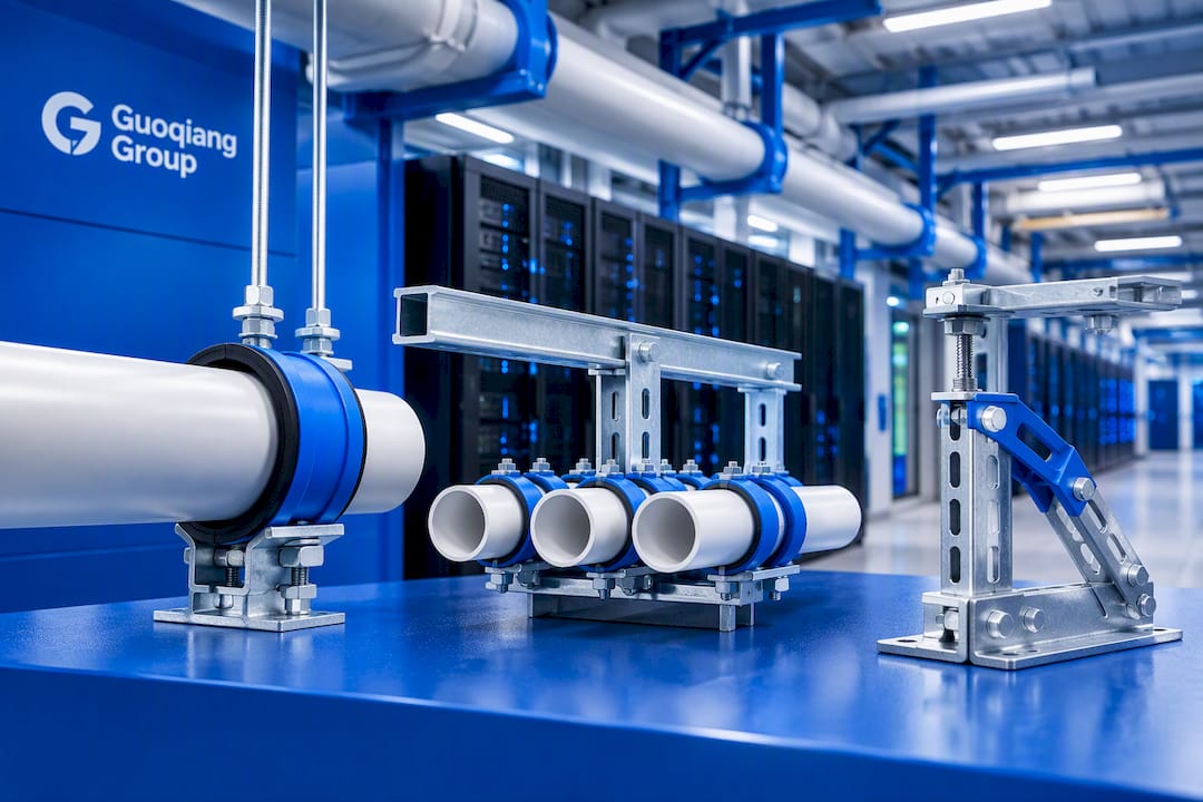
Reach out through our product catalog to request drawings and quotes, or start a conversation about OEM and ODM engineering support if your project needs custom spans, finishes, or seismic documentation built around your site conditions.
FAQ
What is the purpose of a pipe support?
A pipe support carries the weight of piping and its contents while controlling movement from thermal expansion, vibration, and seismic force. In data centers, supports also maintain insulation continuity to prevent condensation at chilled water lines.
What type of piping is used in data centers?
Stainless steel is common for chilled and condenser water loops because it resists corrosion in humid mechanical rooms, while carbon steel is used where cost matters more and coating or insulation offsets corrosion risk. Industry practice is shifting toward ASME B31.3 industrial piping standards for high-density cooling rather than lighter commercial-grade codes.
How often does a pipe need to be supported?
Spacing depends on pipe diameter, material, and whether the line is fluid-filled, with allowable span tables setting the baseline for rigid versus flexible systems. Attachments like valves and flex connectors require additional support points beyond the standard spacing.
What is the code for vertical pipe supports?
Vertical and lateral seismic bracing for piping in the United States is governed by ASCE 7-22 Chapter 13, which sets design force requirements based on occupancy risk category. Data centers typically fall under Risk Category IV, which raises those design forces through an importance factor of 1.5.
How do pre-insulated supports prevent condensation?
Pre-insulated supports mold insulation around the pipe at the clamp or bracket point instead of leaving bare metal exposed, keeping the vapor barrier continuous. This stops the support itself from becoming a cold spot where humid air condenses and drips onto equipment below.
Sources
- Seismic bracing requirements for nonstructural components — Strongtie SE Blog
- Chapter 22. Pipe design — ASHRAE Handbook
Authoritative Standards and Technical Resources
Engineers validating support and anchor calculations should work directly from primary standards rather than secondhand summaries. ASCE 7-22 Chapter 13 sets the governing seismic bracing requirements for nonstructural components including piping. ASHRAE’s piping chapter covers material selection tradeoffs between metallic and nonmetallic pipe. Piping Technology & Products’ data center resource outlines the industry shift toward industrial piping codes for high-density cooling.
MSS SP-127 covers bracing detail practices, ACI 318 governs anchor design into concrete, and ICC-ES evaluation reports confirm an anchor’s qualification for the seismic application. A PE should reference all of these together when stamping a submittal, rather than relying on a single source.