

A dual-loop chilled water system, also called a primary-secondary system, splits the plant into two hydraulic circuits. The primary loop makes chilled water at a steady flow through the chillers. The secondary loop distributes it to the building at whatever flow the load demands. A short common pipe, the decoupler, joins the two. That split lets chillers see stable flow while the building side varies, and it is the reason this layout has stayed a default for large campuses, hospitals and data centers.
This guide explains how the loops connect, how water moves through them, where the energy savings come from, and which operating problems to look for first.
TL;DR
- A dual-loop system separates chilled water production (primary loop, chillers and constant-speed pumps) from distribution (secondary loop, variable-speed pumps) through a common bypass pipe.
- The decoupler gives hydraulic independence: secondary flow changes do not push the chillers into low-flow trips.
- Savings come from slowing secondary pumps at part load, because pump power falls much faster than flow.
- Secondary flow should not exceed primary flow. When it does, supply temperature rises and system delta-T collapses.
- A plate heat exchanger can replace the common pipe when you need true hydraulic separation, for example in tall buildings, at the cost of an approach temperature penalty.
Table of Contents
- What a dual-loop chilled water system is
- How water moves through the two loops
- Why not one pumping circuit?
- Where the energy savings come from
- Designing the decoupler
- Delta-T: the number that decides efficiency
- Plate heat exchanger or common pipe?
- Operating problems and how to diagnose them
- Our perspective on dual-loop piping in demanding facilities
- Piping for primary and secondary chilled water loops
- FAQ
- Sources
What a dual-loop chilled water system is
In a primary-secondary arrangement, the primary loop has pumps that circulate water through the chillers. The secondary loop has its own pumps that send water to the facility, and the secondary piping network connects to the primary network (NYC Energy Tools).
The link between them is a common bypass pipe, the decoupler, that ties the supply and return headers of both loops together. It makes the two loops hydraulically independent, so a flow change in the secondary loop does not directly change the flow the chillers need (CED Engineering).

Think of it as two rooms with a short open doorway. The chiller room wants a constant stream. The building room wants a variable one. The doorway absorbs the difference.
The main components
A typical plant includes:
- Chillers, each with its evaporator flow requirement.
- Constant-speed primary pumps, sized for the chillers’ design flow. Running them at constant speed lowers the risk of chiller trips from insufficient evaporator flow (ACHR News).
- Variable-speed secondary pumps, usually driven by VFDs and controlled from differential pressure (NYC Energy Tools).
- The decoupler, the common pipe between supply and return headers.
- Terminal units and coils with two-way control valves.
- Sensors and a building automation system (BAS), including differential pressure sensors out in the distribution network.
How water moves through the two loops
Primary pumps push a constant volume of chilled water through the chillers. Secondary pumps draw from the primary supply header, send water to the building loads and return it to the return header. The decoupler lets water pass between the loops according to pressure and load balance (CED Engineering).
Three operating states are worth knowing:
| Condition | What happens in the decoupler | Result |
|---|---|---|
| Secondary flow equals primary flow | Almost no flow in the bypass | Ideal balance, typical at full load |
| Secondary flow below primary flow | Surplus supply water flows through the bypass toward the return side | Warmer mixed water returns to the chillers |
| Secondary flow above primary flow | Return water flows backward into the supply side | Supply temperature rises, deficit flow |
When secondary demand drops below primary production, the extra water goes through the bypass and mixes chilled supply water with warmer return water before it reaches the chillers (Trane Air Conditioning Clinic).
At full load, secondary flow normally equals primary flow, and at part load it should not exceed it. If secondary demand outruns primary flow, a deficit-flow condition can raise the supply temperature and produce low system delta-T (Yan, Yang and Xu, Buildings, 2018).
Why not one pumping circuit?
A single constant-flow loop is simple, but it wastes pump energy whenever the building is below peak. A single variable-flow loop saves energy but can starve chillers of flow. Primary-secondary pumping protects chillers from flow sensitivity, which can trip them, while allowing variable flow in the building loop for part-load savings (ACHR News).
In U.S. and European markets it has long been a standard way to get reliable hydraulic separation at a relatively low capital cost (HPAC Engineering).
The decoupling also lets a plant mix chillers of different types or sizes, because flow disturbances do not travel from one chiller to another (Trane Air Conditioning Clinic). That matters for plants that grow in phases, which is common in data center campuses.
Where the energy savings come from
Variable-speed secondary pumps move only the flow the load needs, using only the energy needed to meet demand (Grundfos). The effect is large because power follows a cubic relationship with speed: reduce flow and power consumption drops significantly (CED Engineering).
A quick worked example using the affinity law: a pump slowed to 80% of design speed delivers about 80% of the flow and needs roughly 0.8 cubed, or about 51%, of the power. At 50% speed the ideal figure is about 12.5%. Real systems do not reach the ideal, because static head, motor and drive losses, and minimum-speed limits all intervene, so treat it as a ceiling on savings, not a prediction.
Standard energy codes such as ASHRAE 90.1 favor this type of variable-flow distribution for large complexes, according to CED Engineering’s course material, so that systems can modulate flow during part load (CED Engineering). Check the edition adopted in your jurisdiction before relying on it for a submittal.
To size the savings honestly, you need a realistic part-load profile. Hourly load modelling, such as overheating and dynamic simulation analysis, gives you the hours the plant spends below peak, which is where variable secondary pumping earns its keep.

Designing the decoupler
The decoupler is small, but it decides whether the arrangement works. Trane’s applications engineering stresses that the bypass must be free of significant restrictions to achieve true hydraulic independence and to avoid series-pumping risks (Trane Air Conditioning Clinic).
Practical points:
- Keep it short and straight. Long runs, valves or strainers add pressure drop, and pressure drop pushes flow where you did not intend.
- Size for one chiller. One ASHRAE author sizes the decoupler for a velocity of 15 to 25 ft/s (4.6 to 7.6 m/s) based on a single chiller’s design evaporator flow, to improve flow-measurement accuracy, noting that the traditional approach is to minimize pressure drop (Severini, ASHRAE Journal, 2004).
- Measure the flow. Decoupler flow can indicate excess chiller capacity and help you identify running chillers that can be shut off (Severini).
Decide early which direction of bypass flow your controls will tolerate. Forward flow (supply to return) only wastes some chiller efficiency. Reverse flow dilutes your supply temperature and shows up on the floor as warm rooms.
Delta-T: the number that decides efficiency
Chiller and pump selections rest on delta-T, the difference between return and supply temperature. The same ASHRAE author selects chiller evaporators and primary-pump flow for a delta-T 2°F (1.1°C) below the actual or design coil delta-T, so flow is adequate (Severini). That margin is a design choice, not a code requirement, so discuss it with the plant’s engineer of record.
In practice:
- A high design delta-T means less flow, smaller pipes and lower pumping energy, but it demands coils that really deliver that delta-T.
- Coils that deliver less than design push the plant into low delta-T syndrome: more flow than needed, extra chillers running, and a bypass that carries water in the wrong direction.
- Material choice also matters at higher flow velocities and in aggressive water chemistry. Our guide to stainless steel piping grades covers how 304, 316 and duplex compare for chilled and process water service.
Plate heat exchanger or common pipe?
A common pipe joins the loops hydraulically: water in the primary loop and water in the secondary loop are the same water. A plate-and-frame heat exchanger joins them thermally only. The two fluids never mix, so the flows are fully independent (Cooper Union, 41 Cooper Square case study).
The same case study notes the primary side pressure can stay relatively low, because the primary water does not have to be routed through the whole building, and the secondary flow can be redirected more easily to different zones (Cooper Union).
| Factor | Common pipe (decoupler) | Plate heat exchanger |
|---|---|---|
| Hydraulic connection | Shared water, one pressure system | Fully separated circuits |
| Temperature penalty | None | Approach temperature, so the chiller must make colder water |
| Cost and space | Low | Higher: exchanger, extra pumps, controls |
| Water quality isolation | None | Keeps dirty or treated loops apart from the chillers |
| Typical use | Central plants, campuses | Tall buildings, pressure zoning, separate tenants or process loops |
The approach temperature is the key trade-off. Because heat crosses a plate, the secondary supply is always a little warmer than the primary supply, so the chillers have to run colder to deliver the same temperature to the coils. Choose the exchanger when separation is worth that cost, and the common pipe when it is not.
Operating problems and how to diagnose them
Most field complaints trace to a handful of causes:
- Low delta-T. Compare actual and design delta-T at the coils and at the plant. Fixes include cleaning coils, retuning controls and replacing three-way valves with two-way valves (Severini).
- Reverse flow in the decoupler. Secondary pumps are moving more than the primary can supply. Check pump staging, differential pressure setpoints and whether a chiller is off while its pump is still needed.
- Restricted bypass. A partly closed valve or undersized pipe turns the loops into series pumping.
- Mixed supply temperature. If the supply temperature at the building runs above the chiller leaving temperature, the bypass is feeding warm return water into the supply side.
- Chiller trips at part load. Look at primary pump status and evaporator flow, not only the chiller controls.
Start with trend data from the BAS: primary and secondary flows, decoupler flow if metered, and supply and return temperatures at both headers. Most of the diagnosis is visible in those four trends.
Our perspective on dual-loop piping in demanding facilities
We make high-strength steel and stainless steel piping for data center cooling, so we see dual-loop designs from the hardware side. Our view: the decoupler and pump logic get the attention, but the piping that carries the water decides how long the design performs as drawn.
Three habits we recommend to engineers:
- Design the pipe for the duty, not the drawing. Velocity at the decoupler, expansion of long headers and support spacing all affect noise, leaks and flow. Our notes on pipe expansion loops and data center pipe supports go into the detail.
- Choose the material for the water. Treated, glycol-bearing or high-chloride loops call for different stainless grades.
- Plan for growth. Phased data halls are exactly where primary-secondary plants shine, so size headers and tie-in points for the final load, not the first phase.
A well-built loop is boring. Flows balance, temperatures hold and nobody thinks about the headers.
— Hu
Piping for primary and secondary chilled water loops
If you are specifying headers, distribution mains or annular pipe for an AI or hyperscale data center, we manufacture stainless steel cooling piping in-house with strict quality control, and we support custom project engineering. See our data center cooling piping range or talk to us about your loop layout.
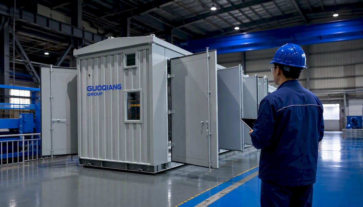
We supply large-scale infrastructure and energy projects and can quote against your drawings and specification. Start from the Annular Pipe Products page or contact us through gq-international.com.
FAQ
What is the difference between primary-secondary and dual-loop chilled water?
They are the same arrangement under two names. The primary loop serves the chillers and the secondary loop serves the building, joined by a common bypass pipe. “Dual loop” describes the two circuits, while “primary-secondary” describes their roles.
Why are primary pumps constant speed?
Chillers need steady evaporator flow, and low flow can trip them. Sizing primary pumps for the chillers’ design flow and running them at constant speed reduces that risk (ACHR News). The variable speed is saved for the secondary side, where load changes.
What should the decoupler flow be at full load?
At full load, secondary flow normally equals primary flow, so decoupler flow should be close to zero (Yan, Yang and Xu). Persistent flow in either direction signals a mismatch in pump staging, controls or coil performance.
When should I use a plate heat exchanger between the loops?
Use one when you need the two water systems to stay separate, such as pressure zoning in a tall building or isolating a treated process loop. Accept the approach temperature penalty and the added cost in return. For a standard central plant, the common pipe is usually simpler.
Sources
- Chilled Water Loop, NYC Energy Tools
- HVAC Chilled Water Distribution Schemes, CED Engineering
- Air Conditioning Clinic: Chilled-Water Systems, Trane
- The Three Stages to Controlling a Chiller and its Primary-Secondary Pumps, ACHR News
- Primary/Secondary-Loop vs. Primary-Loop-Only Systems, HPAC Engineering
- How to configure pumping schemes in HVAC applications, Grundfos
- Primary-secondary chilled water systems, Severini, ASHRAE Journal
- Yan, Yang and Xu, Buildings (2018)