
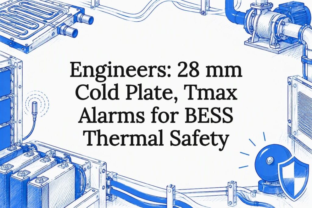
Effective BESS thermal management must control absolute cell temperature and cell-to-cell uniformity while enabling fast thermal-runaway detection and mitigation. That means tracking maximum cell temperature and temperature spread, not rack averages, and backing every cooling claim with configuration-specific test data rather than a vendor data sheet. Get those two things wrong and everything else, from cycle life to insurance underwriting, gets harder.
TL;DR:
- Monitoring maximum cell temperature and temperature spread is essential for accurate thermal risk management, not just average pack temperature.
- Hybrid cooling architectures combining passive and active systems deliver better performance in fluctuating or high thermal loads than single-method solutions.
- Validation of thermal models must include multiple duty cycles and real-world sensor data to accurately predict hotspots and failure paths.
- Procurement should require configuration-specific UL 9540A test reports, as general product family tests do not guarantee safety for specific setups.
- Integrating thermal management with the battery management system enables proactive cooling responses and early fault detection, extending battery life.
Table of Contents
- How Batteries Generate Heat and Why Uniformity Matters More Than Averages
- Thermal Runaway: Mechanisms, Propagation, and the Limits of Cooling Alone
- Cooling Architectures: Air, Liquid, Passive, and Hybrid Systems
- Modeling, Simulation, and Field Validation for Thermal Performance
- Design Best Practices: Cold-Plate Geometry, Coolant Setpoints, and Alarm Thresholds
- Safety Standards and the Procurement Checklist Engineers Should Actually Use
- Guoqiang’s Engineering Perspective on Containerized Thermal Integration
- Integrating Thermal Management with the Battery Management System
- How Thermal Management Affects Battery Life and Degradation
- Cost Trade-Offs Across Thermal Management Technologies
- Emerging Materials: Thermoelectric Coolers and Advanced Phase-Change Compounds
- Environmental and Sustainability Considerations in Thermal System Design
- A Procurement Engineer’s Take on What Actually Predicts Failure
- Ready to Specify a Thermal-Integrated BESS Container
- Sources
- FAQ
How Batteries Generate Heat and Why Uniformity Matters More Than Averages
Heat in a lithium-ion pack comes from two main sources: electrochemical polarization losses and resistive (I²R) heating from internal resistance. Both scale with current, which is why C-rate is the single biggest lever on how hot a pack gets during any given cycle. A cell pushed at 1C generates roughly four times the resistive heat of the same cell at 0.5C, since I²R losses scale with the square of current.
State of charge and ambient temperature compound the problem. Cells run hotter internally near full charge and near full discharge, and a container sitting in direct sun in Arizona starts every cycle from a worse thermal baseline than one in a temperate climate.
The metric that actually predicts failure isn’t average pack temperature. Engineers should track:
- Tmax — the hottest individual cell, not the rack mean
- ΔT — the spread between hottest and coldest cells in a string
- Rate-of-rise — how fast Tmax is climbing, which flags a developing fault before absolute temperature does
A pack can show a perfectly reasonable average temperature while one cell is already accelerating toward failure. That’s the blind spot averages create.
Thermal Runaway: Mechanisms, Propagation, and the Limits of Cooling Alone
Thermal runaway starts with an internal short, a manufacturing defect, or sustained overheating that triggers exothermic decomposition inside a single cell. Once that cell vents, heat propagates to neighbors two ways: through direct conduction across cell-to-cell contact, and through convection as hot gases and ejecta spread through the module. The second pathway is why enclosure design and ventilation matter as much as the cooling loop itself.
No cooling system stops a runaway event already in progress inside a cell. What thermal management can do is buy time and limit propagation to adjacent cells and modules.
- Early gas detection sensors catch off-gassing before flame or smoke appear
- Forced ventilation paths need to be engineered, not improvised, so vented gas doesn’t pool in enclosed spaces
- Responder procedures need to account for stranded thermal energy that can reignite hours after apparent suppression
Standard-driven proof point: UL 9540A evaluates thermal-runaway behavior and fire and explosion hazards at the cell, module, unit, and installation level, and those results directly inform separation distances and suppression choices at the installation stage.
That’s the core limitation procurement teams need to internalize: thermal management and fire-safety engineering are two different disciplines that happen to share a container.
Cooling Architectures: Air, Liquid, Passive, and Hybrid Systems
Four cooling families dominate BESS design today, and the right choice depends on duty cycle, not just capacity.
- Air cooling handles low C-rate applications well because it’s mechanically simple, cheap to maintain, and has no leak risk. It struggles once discharge rates climb or ambient temperatures run high, since air has a fraction of liquid’s heat capacity.
- Liquid cooling removes far more heat per unit volume and holds tighter temperature uniformity across large racks, which is why most high-power containerized systems use it. The trade-off is added complexity: coolant loops need leak detection, corrosion-resistant plumbing, and freeze protection in cold climates where a static loop can crack a cold plate overnight.
- Phase-change materials and heat pipes buffer transient thermal spikes passively, absorbing heat during a fast discharge event without pulling extra electrical load. They’re excellent for redundancy but can’t sustain heat rejection indefinitely since the material eventually saturates.
- Hybrid architectures layer passive buffering against active rejection, so a heat pipe or PCM layer absorbs short spikes while a liquid loop or fan bank handles sustained load. A 2024 peer-reviewed comparative review found that hybrid heat-pipe and PCM combinations, and hybrid heat-pipe and liquid-passive systems, performed especially well under fluctuating or high thermal loads, and that same review ranked hybrid designs highest across balanced metrics covering heat dissipation, dynamic response, safety, and cost.
Pro Tip: Don’t size a cooling system for average duty cycle. Size it for the worst 15 minutes of the worst day the asset will see over its warranty period, then confirm the margin with sensor data from an actual field deployment, not just a simulation run.
Liquid cooling in large containerized systems specifically reduces both peak temperature and cross-rack temperature inconsistency, according to modeling work on a 100 kW/500 kWh container system, where coolant flow rate and ambient temperature were the two dominant variables affecting outcome.
Modeling, Simulation, and Field Validation for Thermal Performance
Design-stage thermal modeling now typically relies on conjugate heat-transfer simulations paired with coupled electrochemical-thermal-fluid models. These tools reveal problems a spreadsheet calculation misses entirely: airflow or coolant maldistribution across a rack, localized hotspots hidden behind a healthy average, and worst-case thermal-runaway propagation paths. Lawrence Berkeley National Laboratory’s conjugate heat-transfer work makes clear that these models only earn trust once validated against field sensor data across real charge and discharge profiles, including fault scenarios, not a single clean duty cycle in a lab.
That single-duty-cycle trap is the most common modeling mistake in the industry. A model tuned to one charge and discharge profile can look perfect in a report and still miss a hotspot that only appears during a rapid-cycling grid-frequency-regulation application.
- Run models against multiple duty cycles, not one representative case
- Validate against calibrated sensor data from an actual installation, not just bench-test cells
- Include fault and derated-cooling scenarios, not just nominal operation
Predictive, AI-assisted control is starting to close part of this gap. Rather than reacting to a temperature reading after the fact, predictive control systems anticipate thermal excursions from load forecasts and coordinate cooling ahead of demand, which cuts parasitic energy draw while preserving the same safety margins.
Design Best Practices: Cold-Plate Geometry, Coolant Setpoints, and Alarm Thresholds
Specific numbers separate a real specification from a marketing claim. Orthogonal experimental testing on serpentine liquid cold plates identified an optimal channel geometry of a few millimeters depth and around 28 mm width, paired with a moderate coolant flow rate per channel, as the configuration that minimized both peak temperature and temperature spread across the module. The same study found coolant inlet temperature has a near-linear effect on outcome: dropping inlet temperature within a typical operational range reduced Tmax proportionally, according to orthogonal cold-plate optimization research.
Cold-plate channel design and coolant inlet temperature frequently matter more than raw chiller horsepower for eliminating hotspots. A bigger chiller compensates for a bad channel layout only up to a point.
Control setpoints should be written into the specification, not left to a vendor default:
- Alarm on Tmax approaching cell manufacturer limits, not container ambient temperature
- Alarm on ΔT exceeding a defined spread across any string, since spread predicts imbalance long before Tmax does
- Alarm on rate-of-rise, which catches a developing fault before absolute temperature crosses a threshold
Liquid-cooled systems carry operational obligations that air-cooled systems don’t. Liquid cooling shifts risk rather than eliminating it, which means the design needs leak detection at every joint, isolation valves that let a technician service one loop segment without draining the whole system, corrosion-resistant materials at every coolant-metal interface, and a defined safe state if the pump or chiller fails, ideally passive dissipation that holds cells below runaway thresholds for a defined grace period.
Safety Standards and the Procurement Checklist Engineers Should Actually Use
UL 9540A is the test method that quantifies thermal-runaway propagation risk, and its results feed directly into NFPA 855, NFPA 70, and NFPA 1 requirements around separation distance, suppression system design, and installation approval. The critical detail procurement teams miss: a UL 9540A report is valid only for the exact configuration tested. Swap the enclosure, the cell chemistry, or the rack spacing, and the test result no longer applies.
Before signing a supply contract, request:
- Cell, module, unit, and installation-level test reports matched to the exact configuration being purchased, not a generic product family report
- Installation instructions referencing the specific separation distances and ventilation requirements the tested configuration assumed
- Configuration-matched evidence confirming the enclosure, cooling architecture, and battery chemistry match what was actually tested, since a revised fifth-edition test on a different pack won’t cover a new configuration
Test outcomes drive real, costly decisions: how far apart containers sit on a pad, whether suppression is required at all, and what a fire department needs to know before responding to an incident on site.
Guoqiang’s Engineering Perspective on Containerized Thermal Integration
That manufacturing scale carries over into containerized energy storage design, where enclosure architecture, HVAC or chiller integration, and sensor routing all have to be engineered together rather than bolted on after the fact. The Mobile PV-BESS Power Station and E-House product forms reflect that integrated approach to containerized thermal design.
Integrating Thermal Management with the Battery Management System
Thermal management and the battery management system (BMS) can’t operate as separate silos in a well-engineered BESS. The BMS owns cell-level voltage and current monitoring; the thermal system owns heat rejection. The value comes from tying the two together so cooling responds to what the BMS already knows about pack state, not just what a temperature sensor reports after the fact.
A well-integrated system lets the BMS throttle charge or discharge current when it detects a cell approaching its thermal limit, buying the cooling loop time to catch up rather than forcing an emergency shutdown. It also lets thermal control anticipate load: if the BMS knows a high-rate discharge event is scheduled, the cooling loop can pre-cool the pack before the event starts rather than reacting once temperature already climbs.
Sensor placement matters enormously here. A BMS reading temperature from only a handful of sentinel cells per module will miss localized hotspots that a denser sensor array would catch, and that gap becomes the exact blind spot that lets a developing fault go undetected until rate-of-rise is already dangerous.
The practical integration points worth specifying in any procurement contract:
- Shared alarm thresholds between BMS state-of-health data and thermal control setpoints, so the two systems agree on what counts as an excursion
- Current derating logic that responds to ΔT and rate-of-rise, not just absolute Tmax
- A communication protocol between BMS and thermal controller fast enough to act within seconds, not the multi-minute polling cycle common in older container designs
Systems that treat the BMS and thermal controller as one coordinated control loop, rather than two independent reporting systems, catch developing problems earlier and run cooling equipment less aggressively overall.
How Thermal Management Affects Battery Life and Degradation
Heat is the single biggest accelerant of lithium-ion capacity fade outside of pure calendar aging. Every cycle spent above a cell’s optimal temperature band trades a small amount of usable life for that cycle’s performance, and those small trades compound across thousands of cycles over a project’s operating life.
Temperature uniformity matters just as much as absolute temperature for degradation, arguably more for asset owners tracking warranty performance. A pack with a 10°C spread between its hottest and coldest cells ages unevenly: the hottest cells degrade faster, their internal resistance climbs, and that mismatch forces the BMS to derate the entire string to protect the weakest cells. One hot corner of a rack can effectively cap performance for cells that would otherwise still have years of healthy life left.
This is where the case for tight ΔT control becomes an economic argument, not just a safety one. A thermal system that holds Tmax within spec but lets ΔT drift wide will still show accelerated capacity fade in a project’s later years, even though nothing ever tripped a safety alarm. Asset owners evaluating a system purely on nameplate cooling capacity, without asking about uniformity performance across the pack, tend to be surprised by degradation curves that diverge from the vendor’s projected warranty curve around year four or five.
Cold-climate deployments add a second dimension: charging a cold cell accelerates lithium plating and permanent capacity loss, which means thermal management’s job includes warming cells to a safe charge temperature, not just cooling them during discharge. A system engineered only for heat rejection, without a heating capability for cold-start conditions, leaves real degradation risk on the table in any climate with meaningful winter temperature swings.
Cost Trade-Offs Across Thermal Management Technologies
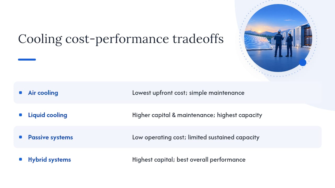
Air cooling wins on upfront cost and simplicity every time, which is exactly why it remains common in lower-rate, lower-density applications where the economics don’t justify a liquid loop. There’s no coolant to source, no pump to maintain, and failure modes are simpler to diagnose in the field.
Liquid cooling costs more upfront: pumps, cold plates, coolant, leak detection, and a chiller or heat exchanger all add capital cost and ongoing maintenance burden that air cooling doesn’t carry. That premium buys real performance, though. Liquid cooling’s higher heat-removal capacity and tighter uniformity typically let a system run at higher C-rates and pack density than an air-cooled equivalent of the same footprint, which changes the calculation from a pure cooling-cost comparison to a cost-per-megawatt-hour-of-capacity comparison instead.
Passive systems, phase-change materials and heat pipes, sit in an interesting middle position. They add material cost but little to no ongoing operating cost since they don’t consume electricity to function. Their limitation is capacity: they buffer transient spikes well but can’t sustain rejection indefinitely, so they work best paired with something active rather than as a standalone solution for continuous high-rate duty.
Hybrid systems cost more than any single technology alone, since a project pays for both the passive buffer and the active rejection loop. The comparative research on balanced performance across heat dissipation, dynamic response, safety, and cost found hybrid designs scored highest overall, which suggests the added capital cost buys enough operational and safety margin to justify itself for many grid-scale applications, particularly those with variable or unpredictable duty cycles rather than steady, predictable ones.
The honest framing for procurement teams: the cheapest cooling system on a quote sheet is rarely the cheapest system over a ten-year operating life once degradation, downtime, and safety margin get priced in.
Emerging Materials: Thermoelectric Coolers and Advanced Phase-Change Compounds
Thermoelectric coolers (TECs) are gaining attention for targeted, precision cooling of specific hotspots within a pack, using the Peltier effect to move heat without any moving parts or refrigerant. Their appeal in BESS applications is precision and reliability: no compressor to fail, no refrigerant to leak, and near-instant response to a localized temperature spike. Their limitation is efficiency at scale; TECs consume meaningful electrical power relative to the heat they move, which makes them a better fit for spot-cooling a known problem zone than for rejecting heat from an entire rack.
Novel phase-change materials are advancing on a different axis: engineers are developing composites that combine a PCM’s latent heat absorption with higher thermal conductivity, often by embedding graphite or metal foam structures into the PCM matrix. A standard paraffin-based PCM insulates almost as much as it buffers, which limits how fast it can shed absorbed heat once the event passes. Conductivity-enhanced composites address that specific weakness, letting a passive buffer layer recharge faster between thermal events, which matters for BESS applications cycling multiple times per day rather than once.
Both technologies remain more common in research literature and early pilot deployments than in mainstream containerized BESS specifications today. Procurement teams evaluating a system that claims either technology should ask for the same configuration-matched test evidence they’d demand for any conventional cooling architecture, since a novel material doesn’t exempt a system from the same UL 9540A validation requirements that apply to a conventional design.
Environmental and Sustainability Considerations in Thermal System Design
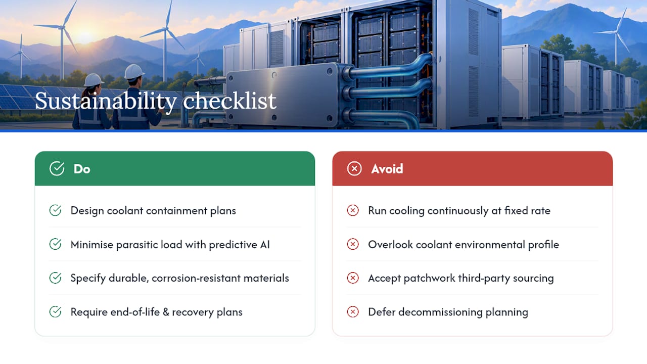
Thermal management carries its own environmental footprint, one that’s easy to overlook when the focus stays on the battery chemistry itself. Liquid cooling loops require coolants that carry their own environmental profile, from manufacturing impact to end-of-life disposal requirements, and a coolant leak into soil or groundwater is a real operational liability that needs containment planning, not just an engineering afterthought.
Parasitic energy load is the more direct sustainability question for most projects. A cooling system that runs pumps, fans, or chillers continuously consumes a share of the very energy the BESS asset exists to store and dispatch, which cuts directly into round-trip efficiency and project economics simultaneously. This is precisely where predictive, AI-assisted control earns its keep: coordinating cooling ahead of anticipated load rather than running continuously at a conservative fixed rate reduces that parasitic draw without sacrificing safety margin.
Material selection matters over a project’s full life cycle too. Cold plates, piping, and enclosures built from durable, corrosion-resistant materials reduce mid-life replacement and the associated material and transport footprint of a component swap twelve years into a twenty-year asset life. Manufacturers with in-house quality control over steel and piping components, rather than a patchwork of third-party sourced parts, have more direct control over that long-term durability outcome, and that durability question is worth raising directly with any supplier during procurement.
Finally, end-of-life planning belongs in the initial specification, not an afterthought once decommissioning arrives. Coolant recovery and disposal, enclosure material recyclability, and cell recycling logistics all vary significantly by system design, and a project specified with disassembly and material recovery in mind avoids the higher decommissioning cost that catches many first-generation BESS projects by surprise.
A Procurement Engineer’s Take on What Actually Predicts Failure
The industry still leans too hard on average rack temperature as its headline KPI, and that habit hides exactly the failures that matter. Trending Tmax and cell-to-cell spread catches a developing fault weeks before an average temperature graph would ever flag anything unusual.
Given the choice, favor layered or hybrid cooling over a single-technology system whenever duty cycles vary, since no single architecture handles both steady-state load and transient spikes equally well. And never accept a UL 9540A citation without confirming it covers the exact configuration on the quote. A test report for a different rack spacing tells you nothing about the system you’re actually buying.
— Hu
Ready to Specify a Thermal-Integrated BESS Container
If you’re comparing cooling architectures, cold-plate suppliers, and standalone HVAC vendors separately, you’re managing three procurement relationships to solve one engineering problem. An effective solution builds that integration into the container itself, drawing on manufacturing capacity behind numerous photovoltaic projects worldwide and in-house steel production that keeps quality control inside one factory rather than spread across subcontractors.
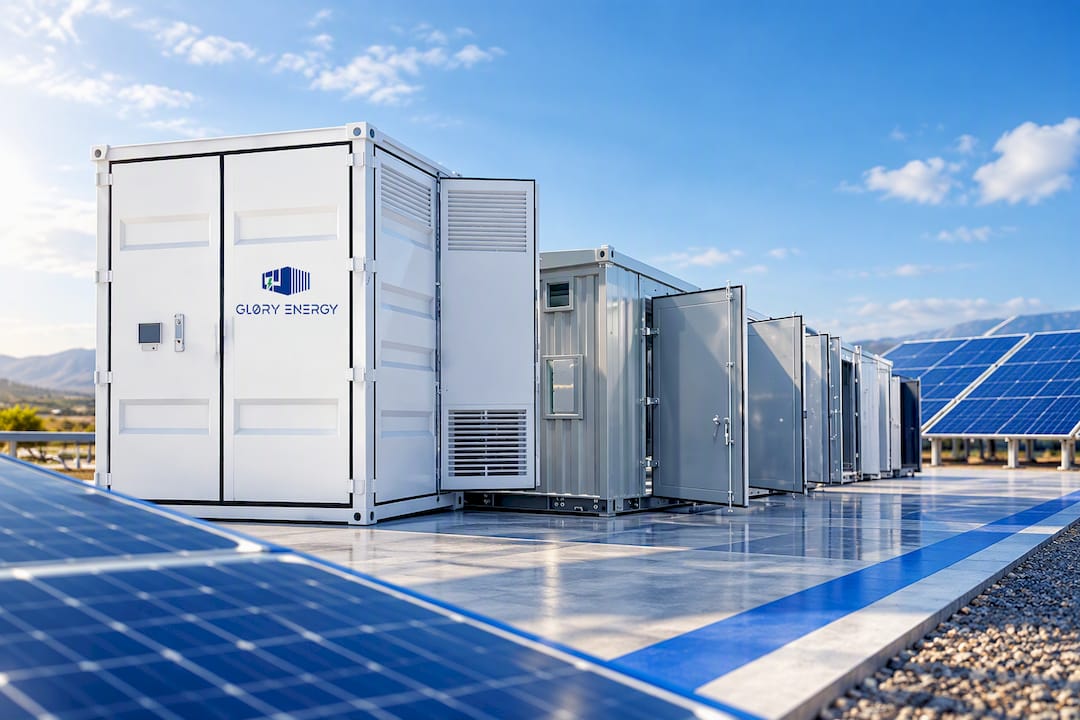
The Mobile PV-BESS Power Station ships with factory-integrated thermal and HVAC options built in, so you’re not retrofitting a cooling loop into a generic enclosure after delivery. The E-House applies the same integrated approach to prefabricated power and thermal enclosures for distributed projects. For coolant distribution and chiller-side piping, Gq-international’s annular pipe products round out the loop. If your project needs custom rack spacing, sensor density, or enclosure dimensions, OEM and ODM engineering support can scope that with you directly. Request configuration-specific test documentation and start a consultation through the Gq-international product catalog to see what fits your next deployment.
Sources
- Comparative Review of Thermal Management Systems for BESS
- Orthogonal experimental-based thermal management design and simulation optimization of a liquid-cooled battery module
- UL 9540A Test Method For Battery Energy Storage Systems
- Conjugate heat-transfer analysis (LBL)
FAQ
What Is the Purpose of Thermal Management in a Battery?
Thermal management keeps every cell within a safe temperature range and keeps temperatures uniform across the pack, which prevents accelerated degradation and reduces thermal-runaway risk. It also enables the BMS to make smarter charge and discharge decisions based on real-time thermal state rather than fixed conservative limits.
What Are the Disadvantages of a BESS?
The main drawbacks are upfront capital cost, the added complexity and maintenance burden of liquid cooling loops, and residual thermal-runaway risk that no cooling system fully eliminates on its own. Site footprint and permitting tied to separation distances from fire-safety codes can also add project cost and timeline.
How Much Does a BESS System Cost?
Cost varies widely based on capacity, cooling architecture, enclosure type, and site-specific engineering requirements, so there’s no single universal figure. Gq-international’s containerized and mobile system pricing is available on request through its product pages.
What Is the Largest BESS in the US?
Large-scale BESS capacity in the US has grown rapidly as grid-scale projects come online across multiple states, with the largest installations reaching into the multi-hundred-megawatt and multi-gigawatt-hour range. Exact rankings shift frequently as new projects are commissioned, so current figures are best confirmed through utility and grid-operator project announcements rather than a fixed number.