
A correct guardrail installation delivers a crash-tested, energy-dissipating roadside barrier that meets FHWA and state DOT specifications, not just a steel rail bolted to posts. Before anyone touches a post driver, confirm the applicable standard drawings, run a site assessment for utilities and clear zone, and schedule utility locates. Highway-grade work also demands crash-attenuating end terminals and correct post embedment. Skip either and you’ve built a hazard, not a barrier.
TL;DR:
- Proper guardrail installation requires confirming standards, running a site assessment, and using crash-tested end terminals for safety compliance.
- Accurate layout, staged tool setup, and assembling posts and rails with controlled alignment are essential to prevent costly rework and ensure effectiveness.
- Fence placement must consider hazard proximity, with utilities, geometry, and clear zones strictly checked to avoid non-standard conditions requiring engineering approval.
- Strong-post W-beam remains the default choice for highway shoulders due to its balance of crash performance and repairability, with material grade and fastener specifications strictly enforced.
- Final inspection involves torque verification, alignment, and thorough documentation to prevent common failures like misalignment, unsealed sleeves, or terminal misorientation.
Table of Contents
- How Do You Install a W-Beam Guardrail Step by Step?
- Site Assessment and Layout: Where Does Guardrail Installation Actually Belong?
- Choosing the Right Rail, Posts, and Hardware for the Job
- What Embedment Depth and Anchoring Practice Actually Works?
- Why End Terminals Determine Whether Your Barrier Protects or Injures
- Post-Installation Testing, Documentation, and Inspection
- How Gq-international’s Hardware Fits Into Standard Installations
- What Safety Gear and Precautions Does Guardrail Installation Require?
- What Goes Wrong on a Guardrail Job, and How Do You Fix It?
- What Actually Separates a Safe Installation From a Liability
- Get Product Drawings and a Quote for Your Next Guardrail Run
- Where to Verify the Final Specs
- Sources
- FAQ
How Do You Install a W-Beam Guardrail Step by Step?
A standard W-beam run follows the same sequence whether you’re working a rural two-lane shoulder or a commercial parking structure edge. The order matters more than the pace. Rushing the layout or torquing bolts before the run is aligned causes more rework than any other mistake on the job site.
1. Mark the layout and calculate length-of-need.
Stake the centerline first, then mark post centers at the spacing called for in your governing standard drawing, typically 6 feet 3 inches for standard W-beam post spacing, though half-post spacing tightens to roughly 3 feet 1.5 inches near transitions and terminals. Length-of-need calculations determine how far the barrier must extend upstream and downstream of the hazard, and the Highway Knowledge Portal lays out the placement rules and minimum-length guidance most state manuals reference. Get this wrong and you’ll either under-protect the hazard or pour concrete and drive posts you’ll need to relocate.
2. Stage tools and equipment before you break ground.
A typical crew needs a hydraulic post driver, a core drill for pavement-mounted sleeves, calibrated torque wrenches, a laser or string line for alignment, and standard rigging for lifting rail sections. Confirm you have the right socket sizes for the fastener grade specified. Nothing stalls a crew faster than discovering the torque wrench on site doesn’t match the bolt spec.
3. Install posts, driven or cored.
Driven posts go in with the hydraulic hammer at the depth your standard drawing calls for. Where pavement or bridge decks prevent driving, core a sleeve, set the post, and grout or mechanically anchor it per the manufacturer’s installation drawing. Assemble rail sections next, and finger-tighten the splice bolts rather than torquing them down immediately. Manufacturer installation documentation, including the single-height rail installation drawing, specifies marking the setout line first and keeping bolts finger-tight through the full run so the crew can adjust alignment before locking anything down. Watch corrugation orientation on every splice; W-beam laps in the direction of traffic flow so a vehicle sliding along the rail doesn’t catch an exposed edge.
4. Install end terminals and attenuators before final torquing.
Terminals and crash cushions get set into position, but hold off on torquing the entire run until the terminal geometry is confirmed. Reflectors, delineators, and end caps go on last, after every structural connection is verified. Installing finish hardware early is a common way to knock components out of alignment during the final adjustment pass.
5. Final torque, alignment check, and cleanup.
Once the full run sits level and true, torque every bolt to the fastener manufacturer’s spec, sight down the rail for consistent height and alignment, and walk the site for debris, exposed anchors, or trip hazards. Photograph the completed run, including post embedment depths where visible and any splice detail, before you leave the site.
| Step | Primary Risk If Skipped |
|---|---|
| Layout and length-of-need | Under-protected hazard or misplaced terminal |
| Tool staging | Wrong torque spec applied, delayed schedule |
| Post installation | Inadequate embedment, rail sag |
| Terminal installation | Exposed rail end becomes a spearing hazard |
| Final torque and cleanup | Loose hardware, undocumented as-built conditions |
Pro Tip: Keep every splice bolt finger-tight until the entire run, terminal to terminal, is staked and sighted for line and grade. Crews that torque section by section almost always end up backing out bolts later to fix a low spot or a kink nobody caught until the last post went in.
Site Assessment and Layout: Where Does Guardrail Installation Actually Belong?
Barrier isn’t warranted everywhere a road has an edge. It’s warranted where a vehicle leaving the roadway would encounter something worse than open ground, a drop-off, a fixed object, a steep embankment, or water. Drop-offs exceeding roughly four feet in depth frequently trigger code or insurer-driven barrier requirements on their own, independent of other hazards nearby.
Before finalizing placement, confirm:
- Length-of-need extends far enough upstream to shield the full hazard zone, with the end terminal sited outside the clear zone whenever geometry allows.
- Underground utilities are located and marked, especially where cored sleeves or driven posts will penetrate more than 4 to 5 feet.
- Pavement edges, shoulder width, and bridge deck transitions won’t force an anchoring method the standard detail doesn’t cover.
- Site geometry, curves, superelevation, or drainage structures don’t conflict with standard post spacing.
Any deviation from a standard drawing, unusual soil, a retrofit into an existing bridge rail, a non-standard slope, warrants a stamped design or direct DOT coordination before you order materials.
Choosing the Right Rail, Posts, and Hardware for the Job
Strong-post W-beam remains the default for most highway shoulders because it balances cost, repairability, and crash performance across a wide range of impact conditions. Weak-post systems, cable barrier, box-beam, and timber-backed rail each solve a narrower problem, lower right-of-way footprint, easier repair after minor hits, or compatibility with rustic corridor aesthetics, but none substitute for strong-post W-beam on a high-speed arterial with a real clear-zone hazard.
Material selection decisions that matter on every job:
- Specify hot-dip galvanized rail and posts for corrosion resistance; coating thickness and post steel grade should match the standard drawing, not a generic hardware-store substitute.
- Match splice bolt and post bolt grades to the fastener schedule in the manufacturer drawing; mixing grades voids the crash-tested assembly.
- Confirm rail orientation and lap direction match the approach traffic direction on every splice, not just the first one.
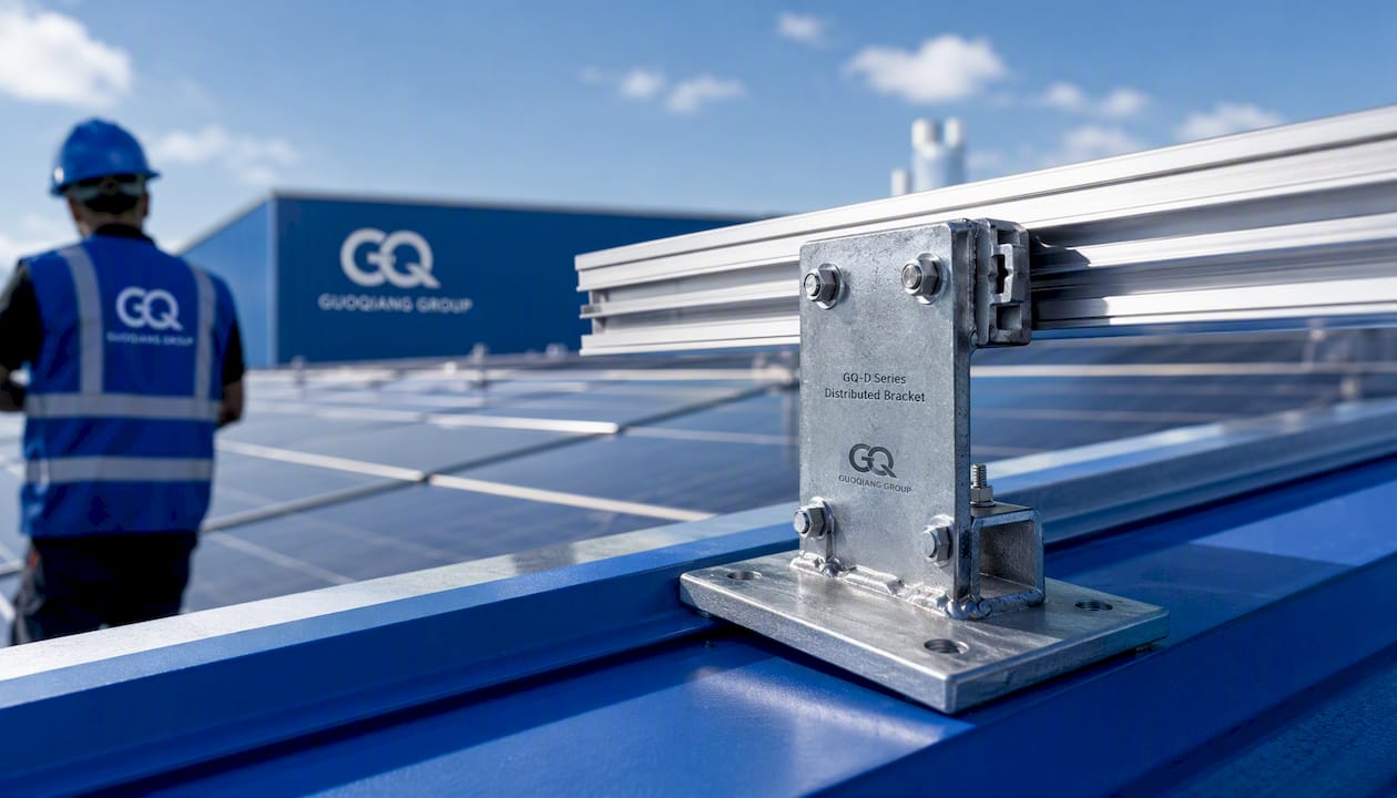
- For continuous-rail runs needing distributed load paths rather than isolated post connections, the GQ-D Series Distributed Bracket offers a bracket option built for compatibility across a continuous run; pull its technical drawings to verify bolt pattern and clearance against your post spacing before ordering.
Whatever system you specify, cross-check every component against the approved materials list in your governing state standard drawings, since substituting an unlisted fastener or post section is one of the fastest ways to fail an agency acceptance inspection.
What Embedment Depth and Anchoring Practice Actually Works?
Embedment is where guardrail installations quietly fail years after the crew leaves. Standard drawings typically call for driven post embedment in the 3.5 to 4 foot range for strong-post W-beam in competent soil, deeper where frost depth or soft subgrade demands it. Cored sleeve installations through pavement need enough sleeve diameter to accommodate post rotation clearance and enough depth to develop the same fixity a driven post gets from surrounding soil.
Field practice that holds up over time:
- Seal the annular gap around every cored sleeve to prevent water intrusion and freeze-thaw cracking of the surrounding pavement.
- Finger-tighten splice bolts across the full run before torquing anything, then align the run visually and by string line before final torque.
- Never torque a section down early just because “it looks fine.” Alignment problems discovered after final torque mean removing hardware you just installed correctly.
- Where frost heave, rock, or subsurface voids prevent standard embedment, stop and request a stamped engineering solution rather than improvising a shallower socket.
Pro Tip: Cored sleeve installations preserve pavement integrity far better than trenching, but only if the sleeve is properly sealed. An unsealed annular gap is a slow leak that turns into a pothole two winters later, right at your anchor point.
Why End Terminals Determine Whether Your Barrier Protects or Injures
An exposed or blunt rail end isn’t a lesser version of a guardrail. It’s a spear pointed at oncoming traffic. Energy-absorbing terminals and crash cushions exist specifically to convert head-on impact energy into controlled deceleration instead of letting a vehicle ride up the rail or impale itself on an unprotected end.
Siting and installation checks that catch the errors inspectors flag most often:
- Confirm the terminal sits outside the functional clear zone of the approach lane wherever geometry permits, with lateral offset matching the manufacturer’s siting guidance.
- Verify anchor embedment and torque on terminal hardware separately from the rail run; terminals often carry tighter tolerances than standard post connections.
- Check terminal orientation against approach direction. A terminal designed for one-directional traffic installed backward defeats its own crash performance.
- Inspect for obstructed clear zone immediately behind and beside the terminal; landscaping, signage, or drainage structures placed too close compromise the terminal’s designed deflection path.
Post-Installation Testing, Documentation, and Inspection
Before you leave the site, run through an acceptance check covering continuity of the rail run, bolt torque across every connection, post spacing against the standard drawing, terminal seating, and confirmation that reflectors and end caps are installed and undamaged.
- Verify rail continuity and splice alignment down the full run.
- Spot-check bolt torque at a sample of connections, including every terminal bolt.
- Confirm post spacing matches the stamped or standard drawing, particularly near transitions.
- Photograph as-built conditions: anchor depths, material lot numbers, and any field deviation from the design.
- Flag and document any non-conformance immediately rather than leaving it for a future inspection to discover.
Routine maintenance after handover should track bent or corroded rail sections, obsolete terminal types due for upgrade, and loosened hardware after seasonal freeze-thaw cycles. Larger agency jobs typically require third-party inspection or formal DOT acceptance before the barrier is considered in service.
How Gq-international’s Hardware Fits Into Standard Installations
Jiangsu Guoqiang Holding Group has manufactured high-strength steel guardrail systems since 1998, and the company holds a domestic market share exceeding 40% in traffic safety products in China, backed by in-house manufacturing and R&D capacity built specifically for transportation infrastructure demands.
That scale matters on the ground because distributed-bracket hardware, like the GQ-D Series Distributed Bracket, needs to behave predictably across long continuous-rail runs, not just in isolated test conditions. In practice, a distributed bracket spreads load connections across multiple points along the rail rather than concentrating stress at individual post connections, which matters on runs with variable post spacing or transition zones. Before specifying it on any job, pull the product’s technical drawings and confirm bolt pattern, clearance, and post compatibility against your site’s standard drawing. Non-standard sites still need a stamped detail; hardware selection doesn’t replace that step.
What Safety Gear and Precautions Does Guardrail Installation Require?
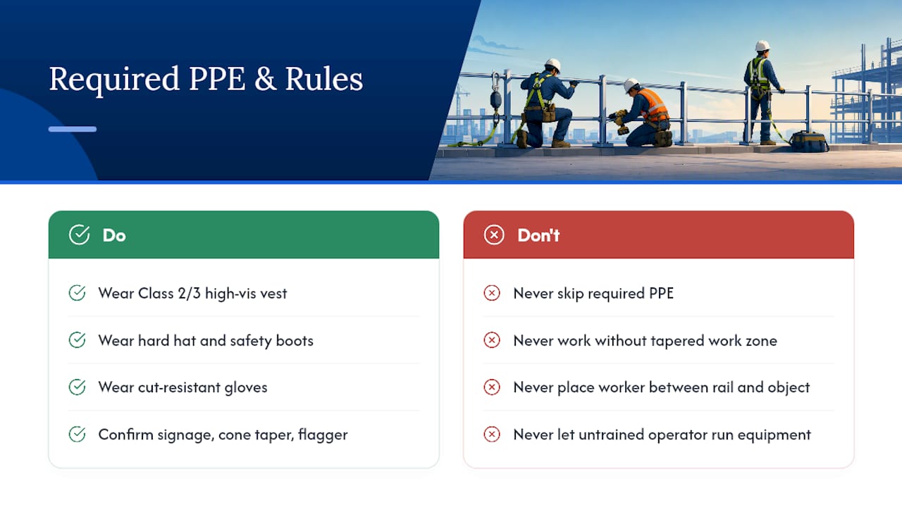
Guardrail work happens on active shoulders, in traffic, near heavy equipment, and around pinch points that catch fingers and hands during rail assembly. Treat PPE as non-negotiable, not situational.
Every crew member on an active installation needs a Class 2 or Class 3 high-visibility vest depending on speed and traffic volume, hard hat, steel-toe or composite-toe boots, and cut-resistant gloves for handling galvanized rail edges, which are sharper than they look. Eye protection is mandatory during any core drilling, cutting, or grinding. Hearing protection belongs in the kit whenever the hydraulic post driver is running for extended periods.
Traffic control matters as much as personal gear. Confirm advance warning signage, cone taper length, and flagger positioning meet your jurisdiction’s traffic control plan before the crew steps onto the shoulder. A crew working within a few feet of live traffic without a properly tapered work zone is exposed to far more risk than any tool on the job site.
Lifting and rigging deserve their own attention. Rail sections are awkward and heavier than they look, and improper lifting technique causes more strain injuries on guardrail crews than almost any other task. Use mechanical lifting aids where the crew size or rail length makes manual handling unsafe, and never position a worker between a rail section and a fixed object during placement. Post drivers and core drills carry pinch-point and kickback risks that demand trained operators only, never a crew member picking up the controls for the first time on site.
What Goes Wrong on a Guardrail Job, and How Do You Fix It?
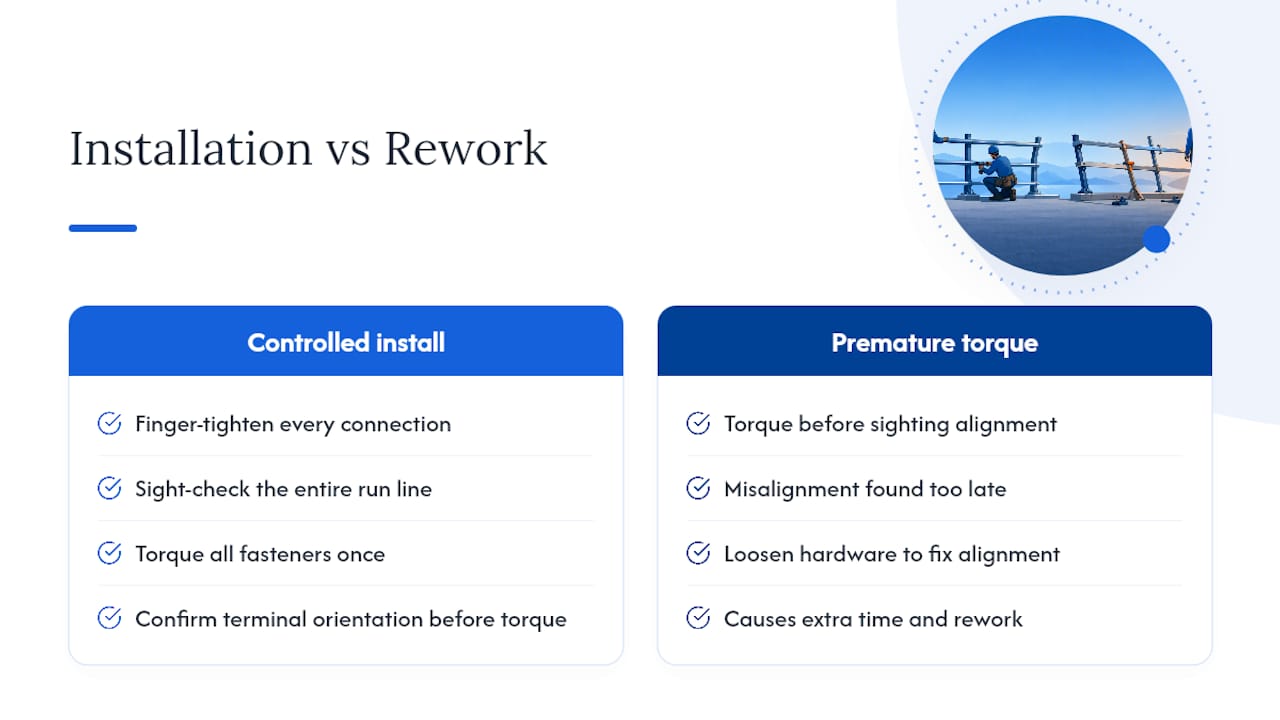
The most common failure point isn’t exotic. It’s misalignment discovered too late, after bolts are torqued and posts are set. A run that drifts even a few inches off line over its length looks fine at a glance but fails a straightedge check, and by the time that’s caught, fixing it means loosening hardware you already tightened. The fix is procedural, not technical: finger-tighten every connection across the entire run before torquing anything, sight the line, then torque once.
Underground utilities are the second most expensive surprise. A crew that skips utility locates and hits a conduit while coring a post sleeve loses the day to repair work and, depending on what got struck, a lot more than that. Locate requests go in before equipment mobilizes, not the morning of.
Pavement-mounted installations bring their own recurring issue: unsealed core sleeves that let water into the annular gap, freeze, and crack the surrounding pavement within a season or two. Seal every sleeve before backfilling, every time, regardless of how the weather looks that week.
Non-standard site conditions, rock, frost, unstable fill cause the fourth common stall point. Crews sometimes try to improvise a shallower post or an off-spec anchor rather than stopping the job. That’s the wrong call. A stamped engineering solution, socketed pedestal, plate anchor, or grout-filled sleeve, takes a day or two to get on paper but avoids installing a barrier that won’t perform as designed under real impact loads.
Finally, terminal misorientation shows up more often than it should on inspection reports. A terminal installed backward or sited without checking the approach clear zone technically completes the punch list but fails its actual job. Double-check terminal orientation against the manufacturer drawing before final torque, not after.
What Actually Separates a Safe Installation From a Liability
Most installation failures trace back to one of three things: embedment that didn’t match soil conditions, a terminal installed without checking orientation and clear zone, or bolts torqued down before the run was properly aligned. None of those require exotic knowledge to avoid. They require discipline in the order of operations.
The bigger judgment call is knowing when to stop. Non-standard soil, an odd retrofit, a slope the standard drawing doesn’t address, these are moments to call an engineer, not improvise a fix that looks close enough. Document everything at handover, photos, embedment depths, material lot numbers, because a thin paper trail is the difference between a quick warranty conversation and a liability dispute two years down the road.
— Hu
Get Product Drawings and a Quote for Your Next Guardrail Run
The company brings extensive experience in high-strength steel manufacturing behind every rail, post, and bracket in its guardrail lineup, supported by in-house R&D designed for crash-performance demands. For contractors specifying continuous-rail runs, the GQ-D Series Distributed Bracket is built specifically for compatibility across long spans and transition zones.
To get a fast, accurate quote, have your linear footage, post type (driven or cored), terminal type, and delivery location ready before you reach out. That’s the information that determines lead time and shipping cost more than anything else. Visit the Gq-international product catalog to download technical drawings, review bolt patterns and clearances against your site plan, and request stamped details for any non-standard installation. Pricing and technical specifications are available on request directly through the site.
Where to Verify the Final Specs
For normative agency requirements, consult FHWA’s guardrail resources and your state’s standard drawings, Kentucky’s included. For product-specific assembly steps, use manufacturer installation drawings, which govern sequencing and hardware, not general design intent.
Sources
Every installation decision should trace back to a document, not a guess. FHWA’s guardrail resources hub hosts guidance on inspection, maintenance, and installation practice along with training and program memoranda relevant to highway work. State DOTs publish their own standard drawings and specifications, Kentucky’s included, which govern dimensions, approved materials lists, and embedment requirements for that jurisdiction.
- Guardrail Resources | FHWA – Department of Transportation
- Guardrail | Highway Knowledge Portal
- GA-001 Rev 3, Single height Rail (installation drawing)
- Kentucky transportation standard drawings
FAQ
What Is the Proper Procedure for Installing Guardrails?
The correct sequence is layout and length-of-need calculation, post installation, rail assembly with finger-tight bolts, terminal installation, then final torque and alignment check. Manufacturer installation drawings, such as the single-height rail assembly guide, document this exact order, including marking the setout line before any post goes in the ground.
How Much Does It Cost to Install a Guardrail?
Costs vary widely by post type, terminal selection, and site conditions, and local contractor pricing typically reflects a per-linear-foot rate rather than a flat fee. Some regional installers report project durations of roughly two to five days for typical residential or commercial runs, though highway-scale jobs with agency coordination take considerably longer.
What Are the OSHA Requirements for Guardrails?
OSHA’s construction and general industry standards govern fall-protection guardrails on job sites separately from highway roadside barrier, so the applicable rule depends on which type of guardrail you’re installing. Highway roadside barrier work falls under state DOT and FHWA crash-performance standards rather than OSHA’s fall-protection guardrail height and load rules, though OSHA’s general PPE and traffic-control requirements still apply to the crew.
How Do I Install a Highway Guardrail?
Start with a site assessment to confirm barrier warrants, length-of-need, and clear zone requirements against FHWA and your state’s standard drawings. From there, follow the standard sequence: stake layout, install posts to the specified embedment depth, assemble rail with finger-tight bolts, install crash-attenuating terminals, then complete final torque and an alignment check before documenting the as-built conditions.
What Makes the GQ-D Series Distributed Bracket Different From Standard Post Brackets?
The GQ-D Series Distributed Bracket spreads load connections across multiple points along a continuous rail run rather than concentrating stress at isolated post connections. Contractors should still pull the product’s technical drawings to confirm bolt pattern and clearance compatibility with their specific post spacing before ordering.