
Good solar cable management means routing, supporting, labeling and protecting every conductor so it survives the full life of the array. In practice that means PV-rated cable, supports that last as long as the modules (not plastic ties), controlled bend radii, no sharp edges, minimal loop area and clear marking. This guide covers each of those decisions for rooftop and ground-mount systems, and shows where the mounting structure helps or hurts.
TL;DR
- Use cable that is rated and listed for PV service, and support it with hardware designed for a 25-year life. Standard plastic ties are the most common point of failure.
- Route cables to avoid sharp edges, standing water and pinch points, and keep string loops small to reduce lightning-induced surge exposure.
- Label strings and circuits at install, not later. It speeds troubleshooting and makes shutdowns safer.
- Plan cable routes together with the mounting design. Rails, piles and purlins are the structure your cables will hang from.
- Check local code (in the US, NEC Article 690 and your local authority having jurisdiction) before you finalize methods.
Table of Contents
- Why cable management decides how long an array performs
- Start with the right cable
- Support hardware: where plastic ties fail
- Routing: the rules that prevent most damage
- Loops and service slack
- Labeling and documentation
- Rooftop versus ground mount
- What to put in the specification
- Our perspective: cable routing starts at the structure
- Mounting systems built around real project constraints
- Pre-install checklist for cable management
- FAQ
- Sources
Why cable management decides how long an array performs
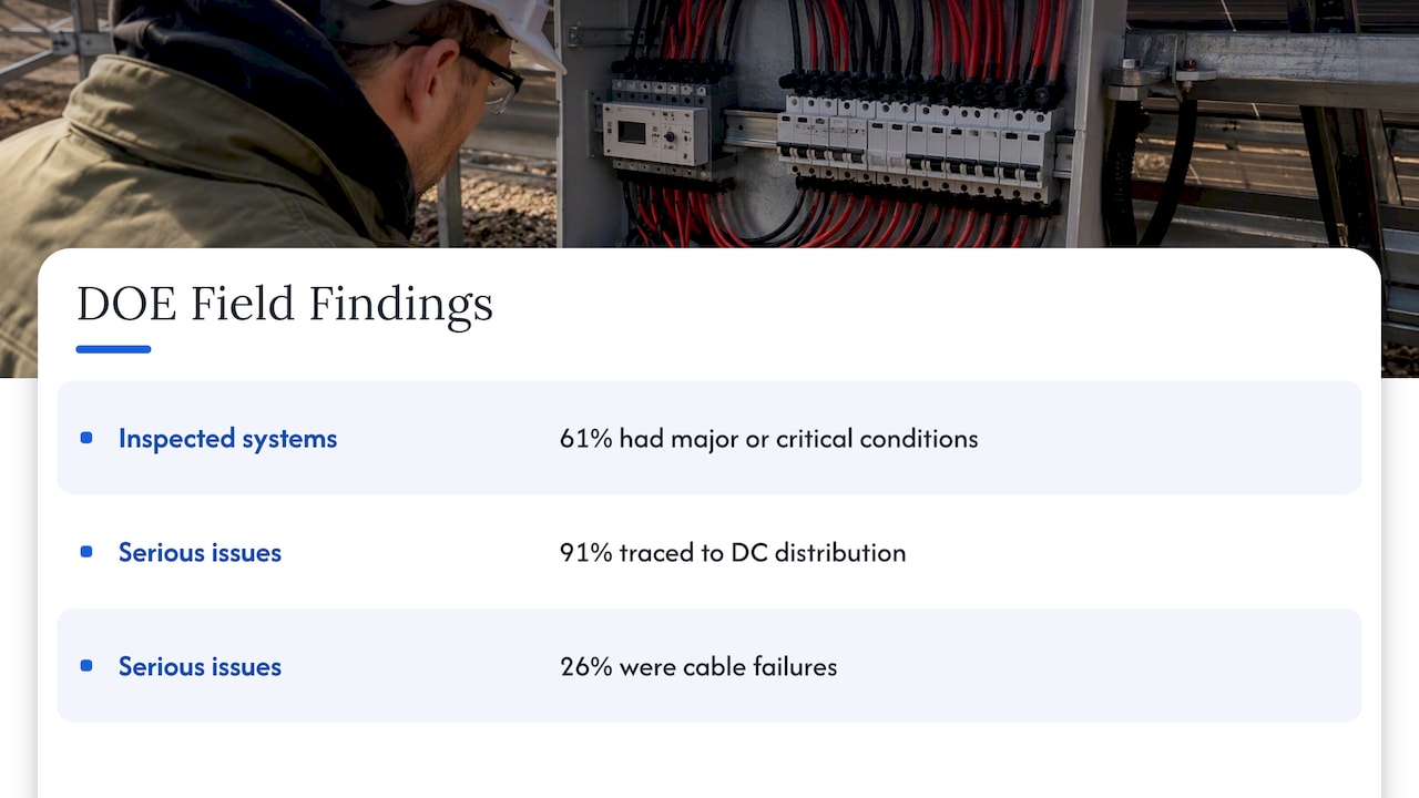
Cables rarely get the attention modules and inverters do, yet they are where many problems start. The U.S. Department of Energy’s Federal Energy Management Program published best practices for supporting DC-string cables that cite field data from about 60,000 systems: 61% of inspected systems showed major or critical conditions, and 91% of those serious issues traced back to the DC distribution system. Cable failures made up 26% of them.
The economics follow from that. Clips, hangers and trays cost little at construction. Repairing a damaged string later can mean dismantling modules, chasing a ground fault across a field and paying a crew to do it. The same DOE document makes this first-cost argument: cheap hardware is the wrong place to save money.
For a project manager or EPC, that makes cable management a specification item, not an installer’s afterthought. Put it in the RFQ with the same clarity as the module, inverter and racking requirements.
Start with the right cable
Support hardware can only protect a cable that was suited to the job. PV cable differs from ordinary outdoor building wire: it is built for sunlight, ozone, wide temperature swings and wet conditions over decades. Standards such as UL 4703 in North America and EN 50618 and IEC 62930 elsewhere describe how PV DC cables handle outdoor exposure, voltage, temperature and insulation integrity.
Two practical points:
- Match the cable to the system voltage. Many utility-scale designs now run at 1,500 V DC, so confirm the cable’s rating before you order, not after.
- Match the method to the code. In the US, NEC 690.31 on wiring methods covers where cable can be used, how circuits are identified and grouped, and when conductors must be guarded or placed in raceway. Check which code edition your jurisdiction has adopted.
If your answer to “is solar cable the same as DC cable?” is yes, be careful. Solar cable is a DC cable, but not every DC cable is a solar cable. PV wire is built and listed for exposed outdoor array use. A generic DC conductor may not be.
Support hardware: where plastic ties fail
Standard plastic wire ties are the most common way installers bundle string wiring, and the DOE flags them as a recurring problem. Their guidance on DC-string cable support points to premature failure from heat, UV exposure and chemical reactivity, and notes that no industry test standard exists for ties in this use. It recommends metallic or PVDF clips and hangers, including stainless steel, as more durable options.
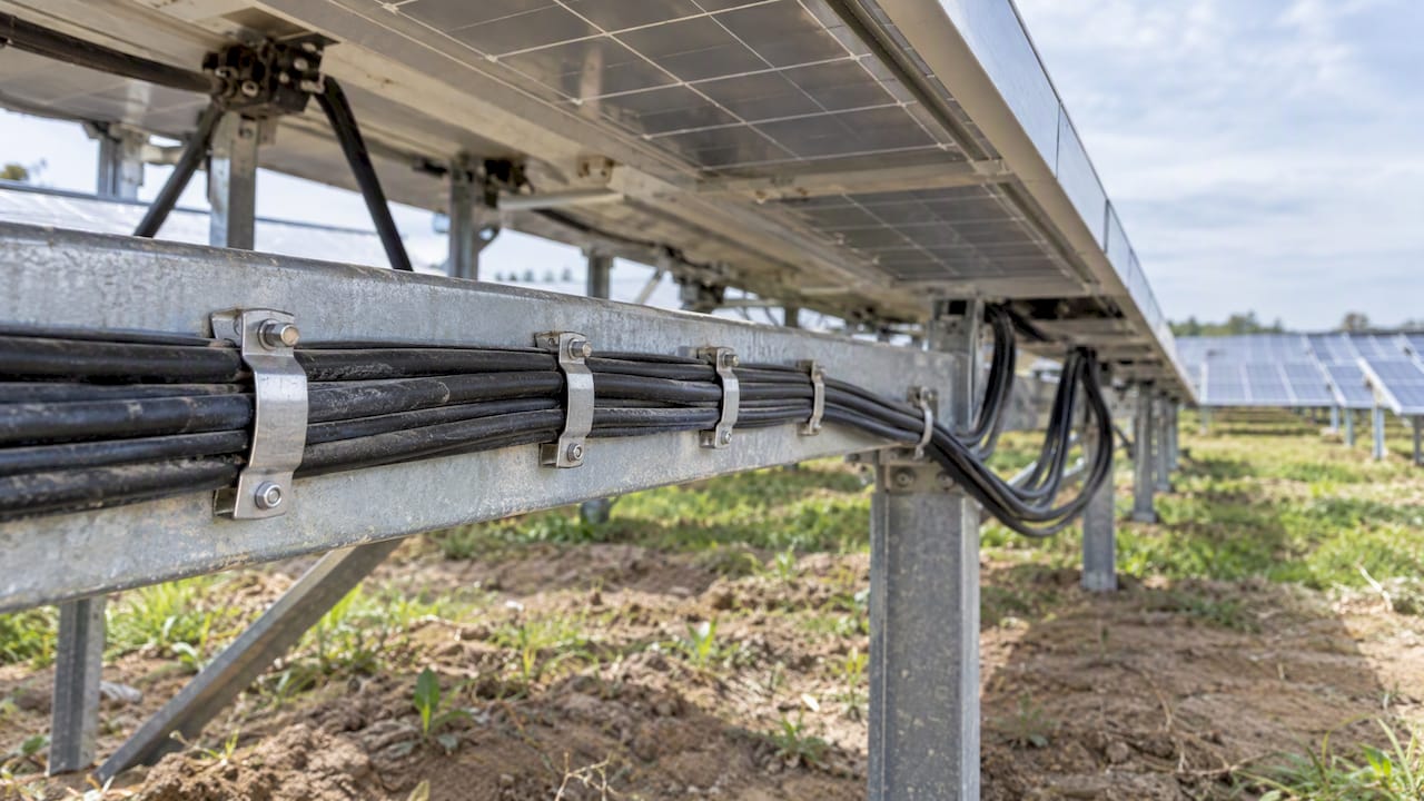
That matters because modules are designed to last roughly 25 years or more. A tie that embrittles in a few summers leaves cable sagging onto roofing, rails or soil, where abrasion and water do the rest.
Choosing hardware by environment
| Environment | Hardware to consider | What to check |
|---|---|---|
| Inland rooftop | Stainless steel or PVDF clips, J-hooks or hangers | UV and temperature rating, sharp-edge contact |
| Coastal or high-humidity | Stainless steel (316 grade) or PVDF | Salt exposure, galvanic contact with rail metal |
| Ground mount, string cables | Clips on racking, wire basket tray, or messenger wire | Allowance for thermal movement of the structure |
| Large utility sites | Above-ground wire management or buried routes in conduit or direct burial cable where permitted | Terminal structure loads, trenching cost, access for O&M |
If you do use ties anywhere, specify the type and marking in writing. The DOE document describes classified, marked types for outdoor use, and the specification should say which one is acceptable instead of leaving it to what is in the truck.
Material compatibility
Stainless steel against aluminum or galvanized rail can create galvanic contact. Confirm the clip’s coating or isolation against the rail material in the manufacturer’s data. This is a detail an installer will not catch on a busy day, which is why it belongs in the submittal review.
Routing: the rules that prevent most damage
Most of what a good routing plan does is keep cable away from things that wear it out.
- Keep to the bend radius. Tight bends stress insulation and the connector entry. Use the cable manufacturer’s minimum, not a guess.
- Protect against edges. Module frame corners, rail ends and cut sheet metal are sharp. Add edge protection or route around them.
- Keep cable off the roof surface and out of water. Cable resting in a pooled gutter or on abrasive roofing will not last 25 years. Installer guidance such as this solar wire management guide makes the same point about wiring that rests in water or rubs on surfaces.
- Avoid pinch points. Cable pressed between a module and a rail, or under equipment feet, is a ground fault waiting for a hot afternoon.
- Keep paths short and direct. Long looping runs add resistance and cost. Plan routes before racking is installed, not after.
- Leave allowance for movement. Arrays expand and contract with temperature. Rigidly clamped cable between two moving parts will eventually fatigue. Supported, deliberate slack protects connectors.
Free-air routing
Cables bundled tightly run hotter than cables with air around them. That is why designers working with larger conductor counts often choose spaced or tray-supported routing over big bundles. If current-carrying capacity is a design constraint, ask your engineer to run the derating calculation for your actual layout rather than relying on a rule of thumb.
Loops and service slack
Two opposite mistakes show up on arrays.
Large loop areas in a string circuit. When positive and negative conductors run far apart, they enclose an area. The Electrical Installation Guide’s note on PV architectures explains that induced currents from lightning are a risk, and that a layout with a minimized loop area is a basic step in surge resilience. Run positive and negative of a string together wherever the design allows.
Uncontrolled coils of excess cable. Leftover length gets coiled and zip-tied to a rail. Loose coils catch wind and debris, and can strain connectors. Instead, calculate the slack you need, support it in a controlled service loop, and cut the rest out of the design.
Labeling and documentation
Cable management is not only physical. A technician opening a combiner at dusk, or a firefighter needing to isolate a section, needs to know what each conductor is. Installer guidance consistently stresses clear marking of strings, DC circuits and AC circuits so that components can be isolated fast during troubleshooting or emergencies.
A workable standard:
- Label every string at both ends with the same ID used in the as-built drawings.
- Use UV-stable, durable labels, not paper tape.
- Mark DC and AC circuits distinctly.
- Photograph the finished routing before covers close, and file it with the O&M package.
- Keep labeling consistent across phases of a site so crews do not need to relearn it.
This also matters on roofs where panels may later have to come off. If a roofer has to lift part of an array for repairs, a system with clear labels and documented routing is far easier to disconnect and put back correctly. Roofing contractors who do solar panel removal and reinstall rely on exactly that kind of clarity.
Rooftop versus ground mount
Rooftop arrays
On roofs, the constraints are different: limited space, roof penetrations, heat from the roof surface and the need to keep conductors off roofing. Standing seam metal roofs deserve a note. Because many clamp directly to the seam, wiring has to be supported from the racking rather than drilled into the panel. A San Diego roofer explains how standing seam metal roofs and solar work together, including material choices for coastal conditions. Our own guide covers how to choose a solar mounting system for metal roofs, which is the right starting point when your cable routing depends on rail layout.
Ground-mount and utility-scale arrays
On the ground, you have more freedom and more to coordinate. String cables can ride on the racking, in wire basket trays, or on messenger wire systems that keep cable above grade and avoid trenching. Above grade, the main design questions are structural:
- Terminal structures. The end post of a tensioned messenger system carries a large horizontal load, quite unlike the mostly vertical load on a standard post. Have your geotechnical and structural engineers review it explicitly.
- Access. Crews need to reach cable without removing modules.
- Wildlife and vegetation. Cable lying on the ground gets chewed, buried and overgrown. Elevated, supported routes help.
- Trenching versus above-ground. Burial can make sense where permitted, but it adds trenching cost, and fault location gets harder.
For utility projects, the foundation decision and the cable decision interact. Our page on cutting foundation count on utility-scale solar racking and our ground-mount installation guide show how the structure sets up everything that hangs off it.
What to put in the specification
If you are writing or reviewing an RFQ, these items prevent the usual disputes:
- Cable type, voltage rating and listing (for example UL 4703 in the US).
- Approved support hardware: material, grade, UV and temperature rating, and marking of any permitted ties.
- A prohibition on standard unmarked plastic ties for permanent support.
- Minimum bend radius and edge protection requirements.
- Loop area limits and rules for service slack.
- Labeling standard and as-built documentation deliverables.
- Environmental class for the site: coastal, high UV, heavy snow, wildfire exposure.
- Who verifies routing at inspection and sign-off.
Our article on five RFQ items engineers need for permit-ready PV mounting standards goes further on the mounting side of the same document.
Our perspective: cable routing starts at the structure
We manufacture high-strength steel, and we see cable management from the structure outward. A cable support is only as stable as the thing it is fixed to. If a rail twists, a post moves or a tracker flexes more than the design assumed, even good clips end up pulling on conductors.
Three points we would give any project team:
- Decide the routing before the racking is final. If you know where cable will run, the mounting design can leave clean paths, attachment points and edge-free channels. Retrofitting cable paths costs more than designing them.
- Treat the support material as part of the design life. The structure is engineered for decades. The hardware that holds the cable should be specified to the same horizon. Steel and stainless parts are our home territory, and we believe in them for this reason.
- Ask for engineering help on project-specific cases. Unusual terrain, high wind or corrosive sites are where standard details run out. Our in-house production and quality control are set up for custom and project-specific solutions, so we would rather be consulted early than called after a problem.
We do not make cable or cable trays. We make the structures those systems depend on, and we want them to be easy to build around.
— Hu
Mounting systems built around real project constraints
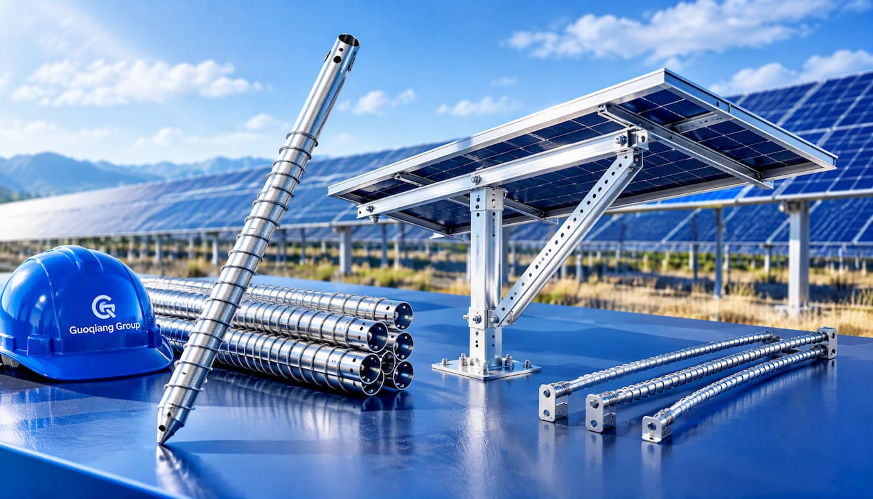
If you are planning a ground-mount or roof project and want routing and structure to work together, our PV mounting system range includes OEM and ODM mounting solutions and project-specific engineering. Our GQ-A Series fixed-adjustable system and GQ-FL series flexible support suit different site constraints, and our photovoltaic pile tube and nail series covers foundations. Prices are quoted per project, so send us your layout and requirements.
Pre-install checklist for cable management
Use this before the crew starts and again before inspection.
- Cable is PV-rated and listed, with a voltage rating that matches the design.
- Routing plan exists and shows string paths, supports and combiner locations.
- Support hardware is stainless steel, PVDF or equivalent, rated for the site.
- No standard plastic ties used as permanent support.
- Bend radius, edge protection and pinch points reviewed on a sample row.
- Positive and negative runs kept together to limit loop area.
- Service slack is calculated and supported, not coiled loose.
- Strings, DC and AC circuits are labeled to match as-builts.
- Photos taken before covers close.
- O&M plan includes periodic inspection of cable supports. The DOE’s guidance on operating and maintaining photovoltaic systems is a useful reference for inspection routines.
FAQ
Is solar cable the same as DC cable?
Not exactly. Solar cable carries DC power, but it is built and listed for exposed outdoor PV use: sunlight, ozone, temperature swings and moisture. General DC conductors may lack those ratings. Always check the listing, such as UL 4703 in the US.
What can I use for cable management on a solar array?
Use clips, hangers, J-hooks or trays made from stainless steel or PVDF, fixed to the racking or a support system. The DOE advises against relying on standard plastic ties for long-term support. If you must use ties, specify a classified, marked outdoor type.
How do I reduce lightning risk in string wiring?
Keep the positive and negative conductors of each string close together to minimize loop area, since larger loops pick up more induced current. Pair that with proper surge protection designed by your engineer and compliant with local code.
Do I need conduit for solar cables?
It depends on location and code. In the US, NEC 690.31 sets rules for wiring methods and says conductors in readily accessible locations above certain voltages must be guarded or in a raceway. Ask your electrical engineer and local authority having jurisdiction before you decide.
Sources
- Solar Photovoltaic Cable Management: Best Practices for DC-String Cables (DOE FEMP, PDF)
- Solar Photovoltaic Cable Management: Best Practices for DC-String Cables (DOE FEMP)
- Life Cycle of Photovoltaic Systems: Operate and Maintain an Existing Photovoltaic System (DOE)
- Solar Cable Standards: EN 50618, IEC 62930, UL 4703
- NEC 690.31 Wiring Methods (ICC)
- Photovoltaic architectures, common characteristics (Electrical Installation Guide)
- Solar Wire Management: Complete Guide To PV Cable Management