
The most reliable way to control welding distortion is to minimize weld volume and heat input, use balanced or skip/back-step sequencing, and constrain the assembly with jigs or fixtures placed close to the weld line. For high-tolerance or large-scale structures, back up these shop controls with FEM or DIC verification before committing to final welds, since prediction catches problems that fixturing alone cannot.
TL;DR:
- Welding heat input should be kept below a critical threshold to prevent sharp increases in out-of-plane distortion, especially on large or restrained assemblies.
- Applying assembly techniques such as balanced welding, strategic tack placement, and fixture placement close to the weld line can significantly reduce distortion and residual stress.
- For large or high-tolerance structures, FEM or DIC methods should be used for pre-fabrication prediction and verification, with fixture constraints optimized to minimize out-of-plane deformation.
- Post-weld correction methods like mechanical or heat straightening carry risks of overcorrection or cracking and should be used only after thorough measurement confirms persistent distortion.
- Planning and engineering support early in the project, including design-for-fabrication reviews, improve distortion control more reliably than relying on after-the-fact repairs.
Table of Contents
- What welding distortion is and the common types fabricators see
- Principal causes and physical drivers behind weld distortion
- Practical prevention techniques for sequencing, tacking, and fixturing
- Measurement, prediction, and verification before and after welding
- Common rectification and post-weld correction methods and their limits
- Applying these methods to large assemblies in PV and energy storage fabrication
- Practitioner perspective: prevention first, measurement for the close calls
- How Guoqiang’s product and engineering offering supports low-distortion projects
- Sources
- FAQ
What welding distortion is and the common types fabricators see
Welding distortion comes from the uneven shrinkage that happens as a weld pool cools. The weld metal and the surrounding heat-affected zone contract as they drop from melting temperature to ambient, and because that contraction is restrained by the colder base metal around it, the assembly locks in residual stress and bends, twists, or bows to accommodate it.
Masubuchi’s classification, widely used across fabrication shops, groups welding distortion into six recognizable modes: transverse shrinkage, angular change, rotational distortion, longitudinal shrinkage, buckling, and longitudinal bending. For shop purposes, it helps to split these into two families:
- In-plane distortion: transverse and longitudinal shrinkage, plus rotational distortion, which shorten or skew a part without taking it out of flat.
- Out-of-plane distortion: angular change, buckling, and longitudinal bending, which lift, bow, or wrinkle the part out of its original plane and are generally harder to correct.
A fabricator sees these play out in predictable ways. A single-pass butt joint on plate often develops angular distortion as the top of the weld shrinks more than the root. A long seam weld on a beam or panel tends to bow along its length. Thin sheet, especially under a continuous weld with excess heat input, buckles into waves because it lacks the stiffness to resist compressive stress. Recognizing which mode is showing up on a given part is the first step toward choosing the right fix, since a technique that corrects angular distortion will not necessarily touch buckling.
Principal causes and physical drivers behind weld distortion
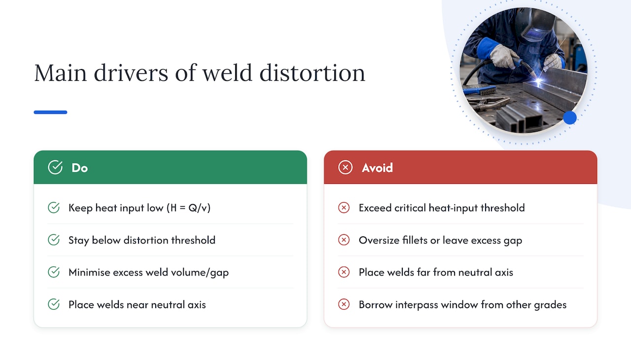
Heat input drives most distortion outcomes, and it is worth quantifying. The standard relationship is H = Q/v, where Q is the arc power and v is the travel speed, giving heat input per unit length of weld. More heat input means a larger, slower-cooling weld pool and a wider heat-affected zone, both of which increase shrinkage and distortion.
The relationship is not linear. Finite element analysis paired with digital image correlation on thin-plate TIG welding found a non-linear link between heat input and out-of-plane distortion, with a critical threshold beyond which distortion accelerates sharply rather than growing in proportion to the extra heat. The practical implication is straightforward: staying below that threshold matters more than any small gain from a faster deposition rate.
Weld volume and geometry compound the heat input effect. A larger bead, an over-sized fillet, or a joint prepared with excess gap all add weld metal that has to shrink, and where that metal sits relative to the part’s neutral axis determines how much that shrinkage turns into bending. Welds placed far from the neutral axis create larger moment arms and more angular distortion for the same volume of weld metal. Restraint works the other way: a stiff, well-braced assembly resists distortion but can trap higher residual stress, while a flexible, unrestrained part distorts more visibly but carries less locked-in stress.
Interpass temperature is a usable control lever on multi-pass welds. A thermal elastic-plastic FEM study incorporating interpass temperature found that accounting for interpass temperature improved angular distortion prediction accuracy and confirmed that the chosen interpass window measurably affects final distortion. High-strength steels need particular care here, since interpass temperatures above a material-specific ceiling can worsen distortion rather than help it, so the window should be validated for the grade in use rather than borrowed from a different material.
Practical prevention techniques for sequencing, tacking, and fixturing
TWI’s fabrication guidance treats assembly technique, welding sequence, and fixturing as the three main levers a shop controls directly, and they work best applied together rather than in isolation.
- Balance the welding around the neutral axis. On double-V or double-side fillet joints, alternate passes between sides so shrinkage on one face is offset by shrinkage on the other; this is one of the most dependable techniques TWI documents for canceling angular distortion.
- Use back-step or skip welding on long seams. Back-step welding lays short lengths in a backward-stepping pattern so each segment’s shrinkage pulls against the previous one, while skip welding distributes shorter welds around the joint instead of running one continuous pass, which spreads heat input and reduces cumulative bowing.
- Tack strategically before final welding. Space tacks according to the approved welding procedure, keep tack length proportional to plate thickness, and tack in a sequence that locks the joint’s final geometry before any long weld run begins.
- Assemble back-to-back where geometry allows. Clamping two mirror-image assemblies together during welding lets each one restrain the other, a technique TWI lists specifically for reducing angular distortion on panel and frame assemblies.
- Fixture close to the weld line. Strong-backs and jigs placed near the joint, rather than at the assembly’s outer edges, resist angular movement directly at the source instead of fighting it after the fact.
- Add stiffeners at the design stage, not as an afterthought. A stiffener welded in the right location raises the section’s resistance to buckling and bowing without adding unnecessary weld volume elsewhere.
Process selection also matters. Mechanized or high-speed deposition processes generally deliver more consistent heat input and travel speed than manual welding, which tends to reduce variability in distortion from one part to the next, though the trade-off is less flexibility to adjust technique mid-weld on irregular geometry.
Pro Tip: When fixtures are limited, asymmetrical joint preparation, cutting slightly more bevel on one side, can compensate for an assembly that cannot be welded from both sides.
For a quick decision path: on small parts with tight tolerances, prioritize fixturing and balanced sequencing first. On long seams or large panels, lead with back-step or skip welding to spread heat input, and add stiffeners or strong-backs wherever the part lacks natural rigidity. On thick, highly restrained assemblies, watch interpass temperature as closely as sequence, since residual stress buildup becomes the bigger risk once the geometry itself resists visible movement.
Measurement, prediction, and verification before and after welding
Shop technique reduces distortion, but on large or high-tolerance assemblies, prediction and measurement catch what fixturing alone misses. Inherent-strain finite element methods derive the local strain field from a small, detailed model of a weld and then apply it to a coarser global model of the full structure, which keeps the computation manageable for large parts without sacrificing accuracy where it matters.
- Use localized models for a single joint or small sub-assembly, where full thermal-mechanical detail is affordable.
- Use inherent-strain global models for large structures, where efficient FEM workflows make whole-assembly prediction practical before fabrication begins.
- Use digital image correlation (DIC) for transient, full-field distortion mapping during welding, which paired with thermal-mechanical FEM gives accurate predictions for designing control measures.
- Use 3D coordinate measuring machine (CMM) checks for final verification, confirming the finished part meets drawing tolerance after any correction.
Jig and fixture placement is not a minor detail in this prediction work. The OSTI study on jig constraints in large structures found that restraint position and pitch are decisive factors, with constraints placed closer to the weld line producing larger reductions in out-of-plane distortion, reporting reductions of up to roughly 40% depending on configuration. That kind of reduction justifies the modeling effort on parts where rework is expensive or impossible, such as large welded structures that cannot be easily unbolted and reclamped. Simulation investment makes the most sense when tolerance is tight, the part is large, or the cost of a failed first attempt exceeds the cost of running the model.
Common rectification and post-weld correction methods and their limits
When distortion still shows up despite good shop practice, correction options are limited and each carries risk.
- Mechanical straightening using a press or rolls applies controlled force to bend the part back toward flat, effective on moderate distortion in ductile material but capable of introducing new residual stress if overdone.
- Heat straightening applies localized heating patterns, often with restraint, to shrink the part back into shape; it demands a documented procedure and an operator who understands how heat placement drives the correction.
- Controlled stress relief through post-weld heat treatment reduces residual stress but does not reliably remove distortion that has already taken a geometric form, so it should not be treated as a substitute for mechanical or heat correction.
Watch for overcorrection, which can leave a part distorted in the opposite direction, and for cracking risk when heat straightening is applied to hardened or high-strength steels without proper preheat control. Final QC should always include a dimensional check, ideally with the same CMM or gauge method used before correction, to confirm the fix actually met tolerance rather than just looking straight.
Applying these methods to large assemblies in PV and energy storage fabrication
A manufacturer founded in 1998 builds high-strength steel guardrails, photovoltaic mounting structures, and energy storage containers at a scale that makes distortion control a design-stage issue rather than a shop afterthought. The same principles apply directly: a PV mounting frame welded with poor sequencing can throw off panel alignment across an array, and a BESS container frame with angular distortion complicates door and panel fit.
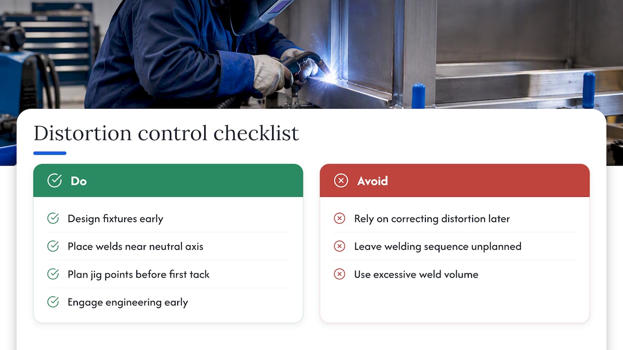
Fixture design and design-for-fabrication, placing welds near the neutral axis, minimizing weld volume, planning jig points before the first tack, matter more as assembly size grows. Engaging engineering support early, before fixtures are built, gives a project the chance to plan jig placement and welding sequence around the specific geometry of a guardrail run or a mounting array rather than correcting distortion after the fact.
Practitioner perspective: prevention first, measurement for the close calls
The instinct to reach for a hammer or a torch after the fact is understandable, but it treats a design and sequencing problem as a repair problem. Prevention belongs at the design and sequencing stage, fixturing and simulation belong on anything tight-tolerance or large, and mechanical or heat correction should be the exception, not the plan.
- Weld volume and heat input are minimized before the first pass is struck.
- Sequencing (balanced, back-step, or skip) is chosen based on joint type and length.
- Fixtures sit close to the weld line, not at the assembly’s edges.
- High-tolerance or large parts get FEM or DIC verification before final commitment.
- Any correction is followed by a documented dimensional recheck.
— Hu
How Guoqiang’s product and engineering offering supports low-distortion projects
Large welded assemblies carry more distortion risk simply because there is more weld metal, more joints, and more opportunity for sequencing errors to compound. The manufacturer’s production applies fixture planning and design-for-fabrication thinking to its product lines, consistent with the principles discussed in this article.
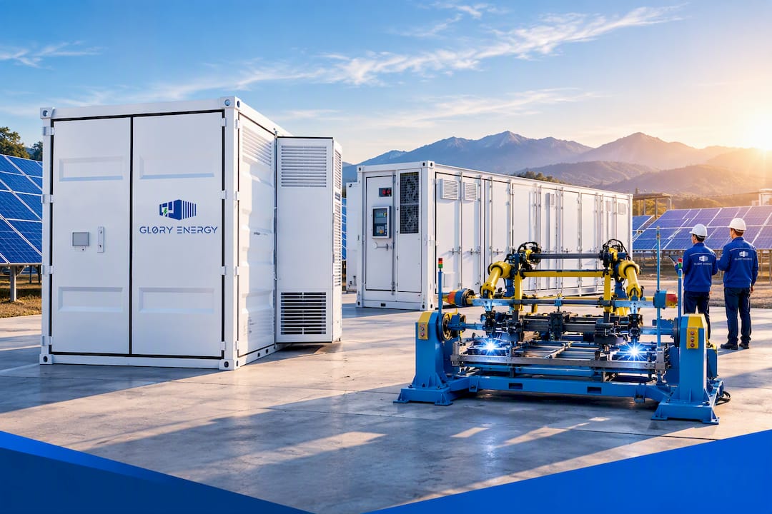
Relevant product lines include the Mobile PV-BESS Power Station, built as a mobile energy storage and generation unit where frame alignment affects every downstream fit, the ODM/OEM Energy Storge Container, and custom OEM & ODM manufacturing for project-specific steel structures.
- Fixture design and jig planning are built into project engineering before fabrication starts.
- Design-for-fabrication review helps catch distortion risk at the drawing stage, not after welding.
- Pre-engineered photovoltaic mounting and energy storage assemblies are designed with alignment considerations incorporated.
Contractors and project engineers who need distortion control planned into a large steel order can review OEM and ODM mounting solutions and project-specific engineering support or browse the full PV mounting, energy storage, and guardrail product range to start a project conversation.
Sources
- Distortion Control – Prevention by fabrication techniques — TWI
- Finite Element Analysis and In-Situ Measurement of Out-of-Plane Distortion in Thin Plate TIG Welding
- Prediction of Welding Deformation Using the Thermal Elastic–Plastic Finite Element Method by Considering Welding Interpass Temperature — PMC
FAQ
Why do welders drink milk after welding?
The practice relates to metal fume exposure, particularly from galvanized or zinc-coated steel, rather than to distortion control. It is a long-standing shop habit with no established protective value against welding distortion itself.
How can distortion be reduced?
Distortion is reduced by minimizing weld volume and heat input, sequencing welds in a balanced or back-step pattern, and fixturing the assembly close to the weld line. On large or tight-tolerance parts, FEM or DIC verification before and during welding catches problems that shop technique alone can miss, with jig placement near the weld line shown to cut out-of-plane distortion substantially in controlled studies.
What is distortion in welding?
Welding distortion is the permanent change in shape or dimension a part undergoes because weld metal and the surrounding heat-affected zone shrink unevenly as they cool. The restrained, uneven contraction locks in residual stress and bends, twists, or bows the assembly away from its intended geometry.
What are the three types of distortion?
Fabricators often simplify Masubuchi’s six-mode classification into broader groups, but there is no single universal three-type system; a common shorthand splits distortion into angular, longitudinal, and transverse categories. Definitions vary across sources, so it is worth checking which classification a given standard or textbook is using before comparing results.