
A pile pull-out test pulls a installed pile upward with a hydraulic jack while instruments record how far it moves at each load. The result is the pile’s uplift (tension) capacity in that soil. In the US, the governing procedure is ASTM D3689. Solar projects lean on it heavily, because trackers and fixed racking put wind uplift on thousands of driven steel piles.
This guide is for engineers, EPC project managers and procurement leads who need to specify, witness or interpret a pull-out test. It covers what the test measures, how to set it up, how many piles to test, and what commonly goes wrong in the field.
TL;DR
- A pull-out test applies a static axial tensile load to a pile and records load against upward movement. ASTM D3689 is the standard test method.
- It is the most direct way to verify uplift capacity. Low-strain integrity testing does not measure capacity at all.
- Reaction frame rigidity, sensor placement and load alignment decide whether your data is usable.
- On solar sites, lateral tests usually come first, then axial tension tests, on test piles installed at different embedment depths.
- Standards compliance alone does not guarantee good data. The competence of the crew and the equipment matter just as much.
Table of Contents
- What a pile pull-out test actually measures
- When you need one: initial tests versus routine tests
- How the test is set up
- Where pull-out tests go wrong
- Reading the results
- Our perspective: design the pile so the test is a confirmation
- Matching test data to your mounting system
- FAQ
- Sources
What a pile pull-out test actually measures
ASTM D3689 covers the minimum requirements for finding the axial movement of a single deep foundation element, or a group, under static axial tensile load. The standard notes that field tests give the most reliable relationship between applied load and axial movement. Results can also help assess how side shear resistance is distributed along the pile.
In plain terms, you get a load-displacement curve. From it you read:
- the load at which the pile moves an unacceptable amount (your capacity criterion),
- whether the pile behaves elastically up to the design load,
- how much permanent movement remains after unloading.
The test does not tell you how the pile will behave under lateral load. That is a separate test, which is why solar geotechnical reports usually present both.
Pull-out testing versus other pile tests
People often lump all pile testing together. The methods answer different questions.
| Test | What it answers | Capacity result? |
|---|---|---|
| Static axial tension (pull-out), ASTM D3689 | Uplift capacity and load-movement response | Yes |
| Static lateral load | Horizontal capacity and deflection | Yes (lateral) |
| High-strain dynamic testing | Estimated bearing capacity from accelerometer and strain data | Estimated |
| Low-strain integrity testing | Shaft continuity, length and cross-section | No |
Low-strain testing, such as pulse-echo, uses a small hand-held hammer impact to assess integrity, cross-sectional area and length. It does not determine bearing capacity. Note also that ASTM lists D5882 as withdrawn in 2025, so check which current standard or owner specification your project calls out before citing it.
Dynamic testing, by contrast, instruments the pile with accelerometers and strain transducers and analyzes the data to assess bearing capacity quickly. It is a different tool for a different job. If your design is governed by uplift, as many solar foundations are, a pull-out test gives the direct answer.
When you need one: initial tests versus routine tests
Geotechnical researchers distinguish two roles. An initial test takes a pile to ultimate capacity and sets the acceptance criteria. Routine tests on working piles then confirm that production piles meet those criteria. In large projects, routine tests are often run on about 0.5% of working piles, rising to as much as 2% depending on the structure, the soil and the required factor of safety. That figure comes from an Indian code document, so treat it as a reference point, not a US requirement. Your project specification and engineer of record set the real count.
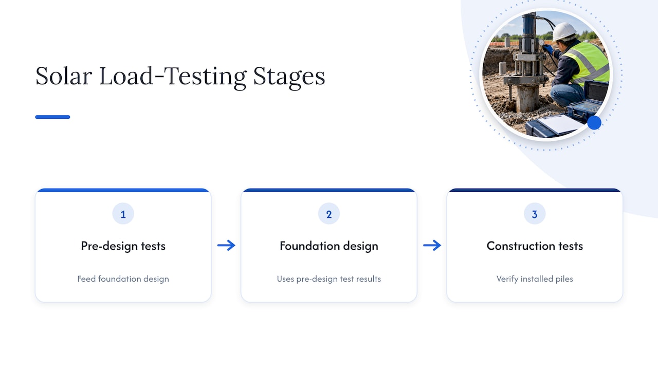
Solar projects add a twist. Because they need thousands of piles, load testing typically happens at two stages: pre-design and construction. Pre-design tests feed the foundation design. Construction-stage tests verify what was installed.
What real solar test programs look like
Public geotechnical reports show the scale:
- One Kentucky project tested 22 locations with W6x9 steel piles.
- A Colorado site drove C8x3 and W8x10 test piles and tested axial and lateral capacity at 60 locations in late summer 2020.
- A Somerset project report describes pile load testing at 38 accessible locations in April 2021.
- A California county appendix documents 36 prototype foundations installed with an impact driver.
The pattern is clear: dozens of test locations, spread across the array area to capture soil variability, not a handful clustered in one convenient corner.
How the test is set up
The basic arrangement
A tension test needs a way to pull the pile up and something to push against. The essentials:
- The test pile, installed the way production piles will be (same driver type, same section, same embedment).
- A loading device, normally a hydraulic jack and pump.
- A reaction system, such as a frame, tripod or anchor piles, that carries the jack’s reaction into the ground away from the test pile.
- A load cell or calibrated pressure gauge to measure applied load.
- Displacement sensors, such as dial gauges or linear transducers, on an independent reference beam.
The generic pile load test layout, a test pile between two anchor piles with incremental loads from a hydraulic jack, is common for compression work. For tension tests on small solar piles, portable frames are more practical.
Loading sequence
ASTM D3689 describes several loading procedures. One of them, the quick test, is widely used for helical piles. One industry explainer says quick test increments are 5% to 10% of the anticipated failure load, held for at least 4 minutes. Check the current edition and your project specification before choosing a procedure, because the specification may require a different one.
Test pairs and embedment depth
A common solar strategy is to install test piles in pairs at different target depths, for example 5 and 8 feet, and benchmark both against design requirements. This tells you how much capacity each extra foot of embedment buys, which feeds directly into pile length and cost decisions.
Engineers often specify both lateral and axial tension testing on PV projects, frequently running lateral tests first and axial tension afterward.
Where pull-out tests go wrong
Most bad data comes from the test rig, not the pile.
Reaction frame rigidity
Terracon’s guidance on solar pile load testing stresses that accuracy depends on the rigidity of the testing system. An unstable reaction frame, poor sensor placement or eccentric loading directly compromises data integrity. A frame that settles into soft ground is a classic cause of invalid results, because the frame movement contaminates your displacement readings. The same guidance recommends custom, rigid, portable tripod apparatuses for site-based solar pile testing.

If you are comparing quotes from testing contractors, ask what the reaction system sits on and how they keep the frame from moving. Ground that is soft or saturated needs bearing mats or a different reaction arrangement.
Improvised loading equipment
Some crews pull piles with an excavator or other construction equipment. That can work for quick checks, but the same guidance warns that hydraulic systems on such equipment are less precise, which creates variability in load application compared with dedicated testing rigs. For a test that sets design capacity, use calibrated, purpose-built equipment.
Alignment and eccentricity
Tension must be applied along the pile axis. Any offset introduces bending and makes the load-displacement curve read stiffer or softer than the real pile. Check the line of pull before the first increment, not after the curve looks odd.
Ground movement near the test
Settlement and soil disturbance around the test area can shift both frame and reference beam. If you see drifting readings during holds, differential ground movement is a prime suspect. For background on how soil settlement is diagnosed and corrected in structures, see this overview of underpinning techniques for differential settlement. It covers building foundations, not solar piles, but the soil behavior logic carries over.
Standards are necessary, not sufficient
The standard itself makes the point: compliance with D3689 does not by itself guarantee reliable results. Quality depends on the competence of the testing personnel and the suitability of the equipment, and agencies are encouraged to meet criteria such as Practice D3740. When you write a specification, require qualified, experienced testing personnel and documented equipment calibration, not just a reference to the standard.
Reading the results
A clean test produces a smooth load-displacement curve. Here is a practical checklist for review:
- Calibration records for the load cell and gauges are attached.
- Reference beam was independent of the reaction frame.
- Load holds show stable readings, or creep is documented.
- Failure criterion matches the project specification, not a default from a template.
- Pile section and embedment match the as-built record for the test pile.
- Soil log for the test location is included, so capacity can be tied to the stratigraphy.
Field teams increasingly use mobile load cells and real-time data entry, sometimes straight into customized spreadsheets, to give immediate visual feedback. That shortens the gap between testing and design review. If a pile fails to meet the criterion on site, you learn it that afternoon and can adjust embedment or pile section before production driving continues.
A note on concrete piles
If your site includes cast-in-place concrete or concrete-filled steel pipe piles and you pair the pull-out test with low-strain integrity checks, timing matters. One method statement says the integrity test should happen no sooner than 7 days after casting, or once the concrete reaches 75% of design strength, whichever comes first. It also notes that grinding the pile head to sound concrete is critical to getting usable data.
Our perspective: design the pile so the test is a confirmation
We manufacture steel foundation and mounting components, and we see pull-out testing from the supplier’s side of the table. Our view is that the best test result is an unsurprising one. That happens when three things line up before the first pile is driven.
First, the pile section and the mounting structure above it are designed as one system. A pile that meets its uplift target but connects awkwardly to the racking creates field problems that no load test will reveal. Our Photovoltaic Pile Tube·Nail Product Series and mounting lines are built with that interface in mind.
Second, consistency in production matters as much as nominal strength. Since 1998 our focus has been high-strength steel made under in-house production and strict quality control, so that the piles you test are representative of the thousands you will install. A test on one pile only tells you something about the others if they are alike.
Third, fewer foundations is a legitimate design goal, but only when test data supports it. If your racking layout can cut the pile count, the pull-out program is how you prove it. We discuss that trade-off in our piece on reducing foundation count with utility-scale solar racking.
Our advice to project managers: put the pull-out program in the schedule before module delivery, budget for at least two embedment depths, and insist on a rigid reaction system. Retesting costs more than doing it right once.
— Hu
Matching test data to your mounting system
Once you have uplift and lateral capacity numbers, they feed the choice of racking. Fixed-tilt, adjustable and tracker structures load their piles differently, and tracker piles typically see more demanding lateral and moment loads than fixed designs. If you are selecting a system, our GQ-F Series Fixed Mounting System and GQ-T Chaoyang Series Tracker System pages are the place to start. For projects with unusual soil, layouts or load cases, our OEM and ODM service supports project-specific engineering. Send your geotechnical report with your enquiry so the discussion starts from real capacity data. For the installation side, see our ground mount solar installation guide.
FAQ
What is the difference between a pile pull-out test and a pile load test?
“Pile load test” is the broad term and includes compression, tension and lateral tests. A pull-out test is the tension version: it applies upward axial load and measures uplift capacity. For solar piles, designers commonly want both the pull-out and lateral results.
Which standard governs a pile pull-out test in the US?
ASTM D3689 covers deep foundation elements under static axial tensile load. It is the reference most US specifications cite. Your project specification may add requirements for loading procedure, failure criteria and personnel qualifications.
Can low-strain integrity testing replace a pull-out test?
No. Low-strain testing assesses shaft integrity, length and cross-section, and it does not determine bearing capacity. If you need to verify uplift capacity, you need a tension load test or a properly justified alternative approved by the engineer of record.
How many piles should be pull-tested?
There is no single number. Research on routine pile testing cites roughly 0.5% of working piles on major projects, potentially rising to 2% depending on soil, structure and safety factor. Solar projects often test dozens of locations in pre-design, so let your geotechnical engineer set the count from site variability.
Sources
- ASTM D3689/D3689M: Deep Foundation Elements Under Static Axial Tensile Load
- Low strain integrity testing specification (pile.com)
- ASTM D5882-16 (withdrawn 2025)
- Dynamic load testing method statement
- IS 2911 Part 4 on pile load tests
- Ensuring Accuracy of Solar Pile Load Testing
- Weirs Creek Solar geotechnical report
- Colorado pull testing report
- Somerset geotechnical report
- San Bernardino County geotechnical investigation
- Understanding and Conducting Helical Pile Load Tests