
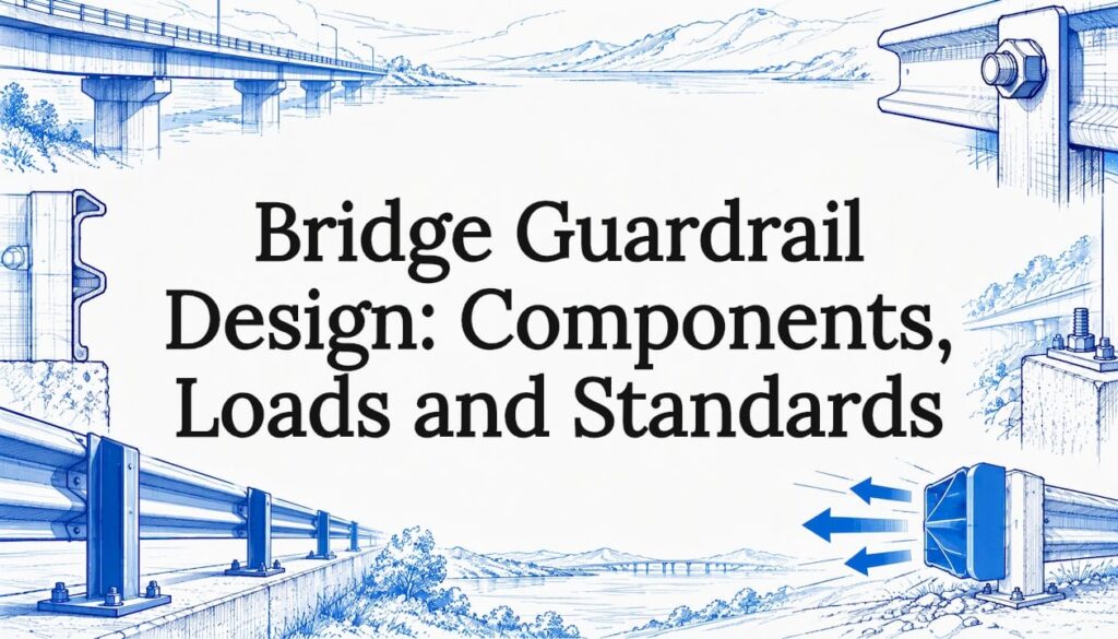
A bridge guardrail is never one product. It is a chain of four parts: the bridge railing, a transition, the approach guardrail and the guardrail end. Each part has to be crash-tested, anchored and matched to the others for the site’s speed, traffic mix and geometry. In the US, the benchmark is AASHTO’s Manual for Assessing Safety Hardware (MASH). Elsewhere it is a regional standard such as EN 1317 or the Austroads bridge barrier guidelines. This guide walks through the design logic in the order an engineer meets it.
TL;DR
- A bridge-guardrail system has four components: bridge railing, transition, approach guardrail and approach guardrail end. Weakness in any one undermines the rest.
- Design is driven by site-specific service level: design speed, traffic volume, share of heavy trucks and site geometry.
- Under US practice the deck overhang is checked for vehicle collision at the extreme event limit state, with a resistance factor of 1.0.
- Standards differ by region (MASH in the US, EN 1317 in the EU, Austroads guidelines in Australia and New Zealand), so confirm the jurisdiction before you pick a product.
- Specify tested, anchored hardware and request the test documentation at tender stage.
Table of Contents
- What a bridge guardrail is designed to do
- The four components of the system
- Design factors that set containment, height and deflection
- Connecting the railing to the deck: loads and anchorage
- Bridge guardrail standards by region
- How to select and verify a design
- Perspective
- Sourcing the roadside part of the system
- FAQ
- Sources
What a bridge guardrail is designed to do
Bridge railings are longitudinal barriers connected directly to a bridge. They keep vehicles and pedestrians from leaving the travel way, according to the Vermont Agency of Transportation glossary. The University of Kentucky’s highway research knowledge portal describes them as barriers intended to stop vehicles running off the edge of a bridge or culvert, physically tied into the structure.
Approach guardrail does a different job. It screens motorists from the hazard beneath or beside the bridge as they approach, and it may shield other roadside hazards too. The same Vermont glossary describes approach railing as the guardrail used to transition from or to the bridge railing.
That difference matters for design. The bridge railing is a structural element, designed with the deck. The approach guardrail is roadside hardware, designed for the roadway. The transition is where the two philosophies meet.

The four components of the system
The Florida DOT structures manual, chapter 9 defines a bridge-guardrail system as four primary components. Here is what each one has to do.
| Component | Role | Design concern |
|---|---|---|
| Bridge railing | Contains and redirects vehicles at the deck edge | Test level, height, strength of deck connection |
| Transition | Joins flexible roadside barrier to the rigid bridge rail | Gradual stiffening, no snagging |
| Approach guardrail | Shields the hazard before the bridge | Length, offset, post spacing, soil or rock embedment |
| Approach guardrail end (terminal) | Safe anchored start of the run | Crash-tested end treatment, ground anchorage |
Bridge railing
The railing may be a concrete parapet, a metal rail on posts, or a combination. Many are designed to have almost no deflection when struck. One widely used reference for US practice gives a minimum height of 42 inches (1.07 m) for the traffic railing, and the exact height depends on the test level you choose.
Transition
A semi-rigid guardrail is flexible. A bridge rail is not. If you join them abruptly, a vehicle can pocket against the rigid end, snag on it or penetrate it. The Kentucky research portal explains that transition sections provide gradual stiffening to reduce exactly those outcomes. In practice that means closer post spacing, nested beam, a rub rail or a curb arrangement, depending on the tested design.
Approach guardrail and its end
The approach guardrail only works if it is anchored. The Florida manual notes that the approach guardrail end is a traffic-friendly anchorage at the end vehicles approach, and that ground anchorage is essential to performance. A rail that cannot develop tension will not redirect a vehicle. For posts set in soil, rock or thin cover, anchor bolt design and embedment checks belong in the calculation package, not in a footnote.
For posts in rock, see our guide to guardrail rock sockets, which covers socket design, backfill and installation.
Design factors that set containment, height and deflection
There is no universal bridge barrier. The Florida manual states that design follows site-specific service level requirements: design speed, average daily traffic, the proportion of heavy trucks, and site geometry.
Test level
Under MASH, barriers are rated by test level (TL-2 through TL-6), and the level rises with impact energy. As an example of how a state turns this into policy, the Iowa DOT railings policy uses standard single slope rails of 38 and 44 inches for TL-4 and TL-5, and requires TL-5 for new interstate mainline bridges. Check your own agency’s manual, as the thresholds differ.
Height
Height governs whether trucks and tall vehicles are redirected rather than rolled over the top. Standard heights usually sit a little above the minimum so that a future deck overlay does not push the rail below its tested height. Iowa’s two extra inches are one documented example of this practice.
Deflection and rigidity
Rigid systems need less space but, per the European Road Safety Observatory motorway synthesis, cause greater physical strain to occupants, especially in passenger cars, than flexible systems. On a bridge you rarely have room for a flexible barrier, so the design question becomes how to get containment with an acceptable occupant severity. Our article on guardrail impact deflection explains how far a barrier moves in a crash and why working width matters for what sits behind it.
Vehicle fleet
The Observatory also points out that growth in vehicle size, especially SUVs and light vans, has increased the number of vehicles that standard barriers do not fully restrain. That is an argument for higher containment levels where heavy or tall vehicles are common.
Design is not a guarantee
The Colorado DOT bridge design manual, section 13 (February 2026) reminds designers that crash mechanics are complex, and that testing cannot assure benign behavior in every incident. Its advice is to use the best available evaluation methods and build in redundancy. That is a good working rule for any project.
Connecting the railing to the deck: loads and anchorage
A tested railing only performs if the deck can take the force it delivers. The FHWA’s prestressed concrete design example states that the deck overhang must be designed for vehicular collision at the extreme event limit state, with a resistance factor of 1.0.
The same example shows that the overhang design typically checks three cases. One of them combines an axial tension force from the collision with the collision moment and the dead load moment. Do not skip that combination. The railing post or parapet base pulls on the deck edge while it bends it.
A practical checklist for the connection:
- Confirm the tested railing’s required anchorage (bolt size, embedment, base plate, reinforcement) from the test report or the agency’s standard drawing.
- Check the deck overhang for the three collision cases, using the railing’s design loads for the chosen test level.
- Verify that edge reinforcement is developed beyond the anchor zone.
- Allow for the overlay thickness that will be added later, so the height stays inside the tested range.
- Detail the transition connection and the first approach posts together with the deck edge, not as separate drawings.
Galvanized steel is a common choice for the roadside parts of this system. Corrosion life then becomes a spec item: see what procurement should require for 50 to 100 year corrosion and the 0.096 in threshold for weathering steel.
Bridge guardrail standards by region
The right standard depends on where the bridge is. The first step in any design is naming the governing document.
United States
The Colorado manual directs engineers to apply AASHTO and MASH criteria, and discusses MASH test levels and evaluation for bridge rails and transitions. For federal-aid projects, the FHWA says new roadside safety devices should meet MASH, and it issues eligibility letters for specific devices. A sample is Safety Eligibility Letter B-259 for a bridge rail. The FHWA notes that it does not regulate manufacture, and that a letter rests on the manufacturer’s and test lab’s submissions. Always check whether your hardware has a letter and whether the range of conditions on it matches your site.
The Florida manual adds that many existing bridge railings do not meet current crash-test standards. Agencies may allow them to stay until replacement is needed, so a rehabilitation job needs a clear decision on what to upgrade.

European Union
The Observatory explains that vehicle restraint systems on motorways must be certified to EN 1317, which classifies performance by containment level, impact severity and working width. Minimum legal requirements for motorway side barriers on bridges vary by country: H4b in Belgium, Germany and Italy, and H1 in the UK.
Australia and New Zealand
Austroads released its Standardised Bridge Barrier Design Guidelines in June 2025, aligned with AS/NZS 5100, AS/NZS 3845 and AASHTO MASH. Austroads also ran a full-scale test in July 2023 with an articulated truck at 90 km/h, against the 80 km/h MASH test speed.
Quick comparison
| Region | Governing framework | How performance is classed |
|---|---|---|
| United States | AASHTO LRFD and MASH, plus state DOT manuals | MASH test levels TL-2 to TL-6 |
| European Union | EN 1317, national minimums | Containment level, impact severity, working width |
| Australia and New Zealand | Austroads guidelines, AS/NZS 5100 and 3845 | Aligned with MASH test levels |
How to select and verify a design
The Florida manual says to select the railing using roadway speed and National Highway System location, then choose a test level that suits the specified conditions. Here is a workable sequence.
- Name the jurisdiction and the owner’s manual. Many agencies add rules on top of the national standard.
- Set the service level. Record design speed, traffic volume, truck share and geometry (curvature, height above grade, what lies beneath).
- Ask whether a barrier is needed. The Observatory advises prioritizing site redesign that removes the hazard, with barriers as the secondary option.
- Pick the test level and railing type. Choose from agency standard designs or devices with a crash-test record.
- Design the deck connection. Run the overhang checks above.
- Match the transition and approach rail. Use a tested transition for your exact combination of bridge rail and guardrail.
- Specify the end treatment and the anchorage.
- Collect the paperwork. Test reports, eligibility letters, galvanizing certificates and drawings should be tender requirements. Our note on tender specifications shows how missing documents sink bids.
An Iowa DOT study on low-volume roads (2010) found that bridge rail and approach guardrail shield more hazardous objects and redirect vehicles, but add initial and maintenance cost and are themselves an object that can be struck. That is why length, end treatment and maintenance access deserve as much attention as the rail.
Mistakes that cost projects
- Mixing parts from different tested systems without a tested transition.
- Ignoring overlay thickness, which lowers effective height.
- Leaving the end treatment or anchorage to the installer.
- Treating the installation spec loosely. See three spec mistakes that make installation liable.
Perspective
Most guardrail failures we hear about are not failures of steel. They are failures of the joint between two good parts: a rail that was never anchored as tested, or a transition that was improvised on site.
Our position is that the approach side of a bridge deserves the same discipline as the deck. Jiangsu Guoqiang has manufactured high-strength steel guardrails since 1998, and our approach is in-house production with strict quality control, so that posts, beams and fittings arrive consistent from the first order to the last.
We would rather an engineer ask us for the galvanizing record, the material grade and the drawing set at the start of a project than discover a gap at installation. For large road and bridge programs, consistent supply of the whole roadside run is what keeps the system behaving the way it was designed.
Hu
Sourcing the roadside part of the system
For the approach guardrail and its steel components, we supply galvanized steel guardrails and wider highway guardrail systems to government agencies, contractors and EPC firms, and we build custom steel infrastructure products to project drawings. Prices are quoted per project, so send us your drawings and quantities.
To discuss a project, start from our guardrail systems page or contact us through gq-international.com. If you also need a median solution, see our median barrier selection guide.
FAQ
What is the difference between a bridge guardrail and a bridge barrier?
In practice the terms overlap. Agencies usually say bridge railing for the barrier attached to the structure, and guardrail for the flexible roadside barrier on the approach. A complete system uses both, joined by a transition.
What height should a bridge railing be?
It depends on the test level and the agency. One common US reference gives a minimum of 42 inches (1.07 m), and states such as Iowa use 38 or 44 inches for their TL-4 and TL-5 standard rails. Use the owner’s manual and the tested device’s documentation.
Which standard applies to my bridge?
The one set by the jurisdiction that owns the road. In the US that means AASHTO and MASH plus the state DOT manual. In the EU it is EN 1317 with national minimums, and in Australia and New Zealand the Austroads guidelines. Ask the road owner which edition applies.
Do I need a transition if the approach guardrail is already installed?
Yes, wherever a flexible guardrail meets a rigid bridge rail. The transition gives gradual stiffening so vehicles are not pocketed, snagged or allowed to penetrate. Use a tested transition that matches both the rail and the guardrail.
Sources
- Vermont Agency of Transportation, Structures and Hydraulics glossary
- University of Kentucky, Bridge Railing and Guardrail Transition Sections
- Florida DOT, Chapter 9 Railing Systems and Safety Features
- European Road Safety Observatory, Motorways
- Colorado DOT, Bridge Design Manual Section 13 Railings
- FHWA, Prestressed Concrete Design Example
- Austroads, Bridge barrier design guidelines
- Iowa DOT, Bridge Rail and Approach Railing for Low-Volume Roads
- Iowa DOT, Railings policy
- FHWA, Safety Eligibility Letter B-259
- Anchor bolt design guidance