
Guardrail impact deflection is how far a barrier moves sideways, away from traffic, when a vehicle hits it, measured until the barrier stops the vehicle’s outward motion. It is not a defect. It is how a flexible or semi-rigid barrier spends crash energy. But the number you design around is usually not deflection alone. It is working width, which also counts the vehicle and any barrier part that swings out. This article explains both measures, what drives them, what standards say, and what to do when a site has less room than the tested system needs.
TL;DR
- Deflection is the lateral movement of the barrier’s traffic face under impact. Working width is the full envelope, from the original traffic face to the farthest point reached by any part of the system or the vehicle.
- Flexible barriers move more and generally soften the crash. Rigid barriers move little but stop the vehicle more sharply.
- Place hazards behind the rail using working width, not rail movement alone, and use test data for the exact installed configuration (post spacing, curb, slope).
- If clearance is short, remove or relocate the hazard, stiffen the rail locally, or choose a lower-deflection system.
- Test results are only valid for the tested conditions, so engineering judgment is part of every layout.
Table of Contents
- What impact deflection means
- Deflection, working width and permanent deformation
- What drives how far a barrier moves
- How standards frame acceptable movement
- Clear space behind the rail
- When the site has less room than the tested width
- After the hit: repair and traffic control
- Perspective: what we see from the supply side
- Specifying a barrier with deflection in mind
- Guardrail systems from Guoqiang
- FAQ
- Sources
What impact deflection means
New York State DOT’s barrier design guidance defines deflection distance as the lateral distance the barrier’s outside face moves under an errant-vehicle impact before the barrier stops the vehicle’s outward movement. The same guide notes that it varies with vehicle weight, speed, impact angle and barrier rigidity.
That makes deflection a trade. A flexible system gives way, lengthens the stopping distance and generally lowers the lateral deceleration the occupants feel. A rigid system barely moves, so it needs no clear space behind it, but it imposes a sharper deceleration. A Canadian roadside design guide puts it plainly: flexible systems give a relatively soft impact and deflect significantly, while rigid systems do not.
The same guide groups barriers by design deflection:
| Category | Typical design deflection | Example |
|---|---|---|
| Rigid | Not significant | Concrete barrier |
| Semi-rigid | Generally 1.5 m (about 5 ft) or less | W-beam on steel posts |
| Flexible | Up to 3.5 m (about 11.5 ft) or more | High-tension cable |
So the right question is never “which barrier deflects least?” It is “which barrier gives acceptable occupant risk while fitting the space the site actually has?”
Deflection, working width and permanent deformation
Three terms get mixed up, and mixing them causes layout errors.
Dynamic deflection is the maximum traffic-side movement of the test article from its pre-impact position during the crash. Test labs usually get it from high-speed imagery and tracked points on the rail or posts, as the University of Nebraska safety research group explains in its Q&A.
Working width is the distance from the initial traffic face to the farthest dynamic position of any major barrier or vehicle component. The Transportation Research Board defines it similarly: the initial traffic face of the restraint to the maximum dynamic lateral position of any part of the system under impact.
Permanent deformation is the residual displacement left after everything stops. It is what a maintenance crew sees on the shoulder the next morning, and it is always the smallest of the three.
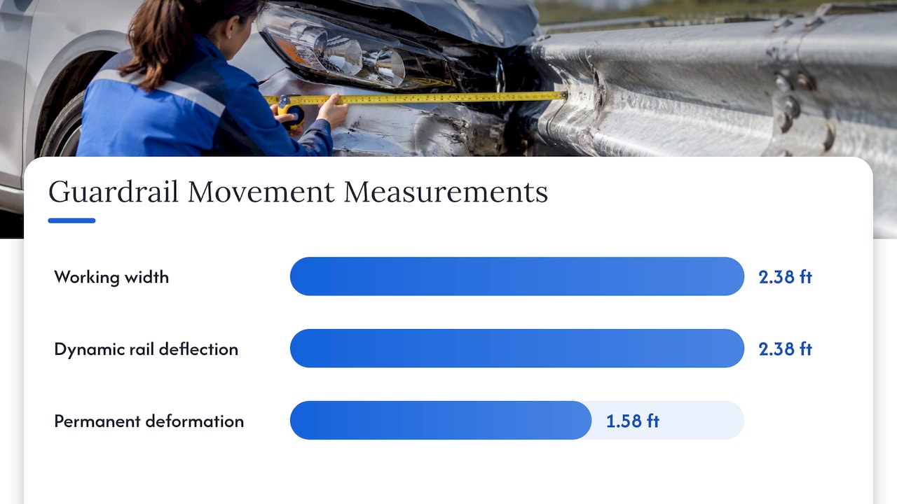
A MASH crash-test report on a 31-inch W-beam guardrail shows the difference in numbers: 2.38 ft working width, 2.38 ft maximum dynamic rail deflection and 1.58 ft maximum permanent deformation. In that test the rail and the working width coincided. They do not always.
The vehicle can govern. The UK’s DMRB CD 377 notes that working width may be set by the vehicle rather than the barrier when the vehicle body deforms around the system. A tall truck leaning over a rail, or a car body wrapping a post, can reach farther than the rail face does. That is why TxDOT warns that working width, not merely rail deflection, should govern longitudinal-barrier placement. The Nebraska group takes the same view: working width is the more useful layout measure because it defines the whole envelope occupied by the barrier or the vehicle.
What drives how far a barrier moves
Four variables set deflection, per New York State DOT: vehicle weight, speed, impact angle and barrier strength. The agency’s published estimates come from crash tests with a standard 2,000 kg vehicle, with a reference condition of 100 km/h and 25 degrees. Lower speeds and narrower roads generally mean less deflection.
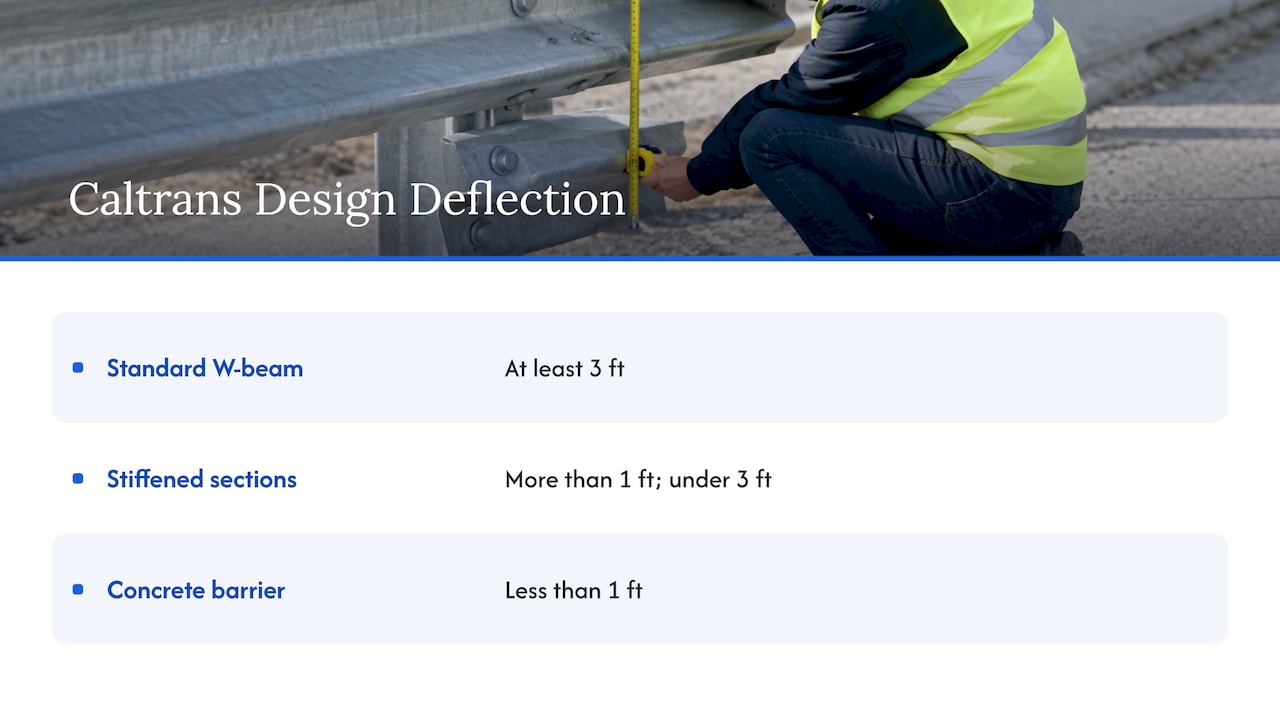
Caltrans uses the same logic in US units. Its roadside safety field guide bases design deflection on a 62-mph impact at 25 degrees using an NCHRP Report 350 or MASH pickup truck, and warns that field deflection can be greater or less depending on real impact conditions. It lists design deflection of at least 3 ft for standard W-beam, less than 3 ft but more than 1 ft for stiffened sections, and less than 1 ft for concrete barrier.
Beyond those four, the installed configuration matters a great deal. Delaware DOT’s semi-rigid barrier training module, along with Ohio DOT guidance, shows that post spacing, curbs, approach slopes and system configuration can materially change tested deflection and working width. A number from one catalog sheet does not transfer to a different post spacing or a rail sitting behind a curb.
The test vehicle matters too. If your specification still cites the older 2,000 kg pickup from NCHRP 350, read our note on what engineers must verify between MASH and NCHRP 350, because the heavier MASH pickup changes what a tested system has proved.
How standards frame acceptable movement
Standards do not set one universal deflection limit. They set a test, pass criteria, and a way to classify the result so that agencies can choose.
United States: MASH and the Roadside Design Guide
The AASHTO Manual for Assessing Safety Hardware uses full-scale crash testing to evaluate direct-impact performance, judging occupant risk, structural adequacy and post-impact vehicle behavior. It also calls for engineering judgment when test results are applied to field conditions that differ from the test.
In practice, the test article must contain and redirect the vehicle or bring it to a controlled stop. In the MASH test 3-10 report cited above, controlled lateral deflection is acceptable, while penetration, underride or override is not. The same report records an occupant-risk criterion that maximum roll and pitch not exceed 75 degrees.
A large deflection that contains the vehicle passes. A small deflection that lets the vehicle vault over the rail fails. Deflection is a design input, not a score.
Europe: EN 1317 classes
Under EN 1317, working width is sorted into classes W1 through W8, rising with deformation. The European Road Federation explains that normalized dynamic deflection is measured in metres from the initial traffic face to the barrier’s maximum displacement, while working width captures the maximum lateral position of the system. National rules decide which class a designer should select. If you supply to projects outside the US, this is the vocabulary the client’s engineer will use.
Clear space behind the rail
The rule of thumb is simple. Delaware DOT’s module states that AASHTO Roadside Design Guide Section 5.6.1 calls for the barrier-to-obstruction distance to be no less than the barrier’s dynamic deflection for the applicable test level. TxDOT’s caution above pushes designers to use working width when vehicle or component reach is larger.
Ohio DOT’s field guide says minimum barrier clearance, or working width, is measured from the barrier face to the obstacle face and varies with configuration. Its 2026 guide lists a MASH 2016 TL-3 MGS guardrail at 5 ft working width with standard post spacing, 3.5 ft with half post spacing and 3 ft with quarter post spacing.
That single example shows the lever you have. Closing up the posts roughly halves the room needed, at the cost of more steel and more posts to drive.
A worked example
Say a bridge pier column sits 4 ft behind the face of a proposed rail, and the system you are considering lists 5 ft working width at standard spacing.
- Standard spacing: 5 ft needed, 4 ft available. The column sits inside the envelope. Not acceptable as drawn.
- Half post spacing, if tested for that system: 3.5 ft needed, 4 ft available. It fits with 0.5 ft in hand.
- Alternatives: a stiffer or rigid system that needs less than 1 ft, or moving the rail face farther from the pier if the shoulder allows.
The figures here are illustrative, drawn from the Ohio listing, and your real values must come from the test report for the exact configuration you will install.
When the site has less room than the tested width
New York State DOT policy requires selected barrier deflection to be less than the lateral distance to the nearest hazard that cannot be removed or relocated. Work through the options in this order:
- Remove or relocate the hazard if it can move. Removable hazards inside the deflection distance should go.
- Stiffen locally. If an unavoidable obstruction is closer than normal deflection, the NYSDOT guidance allows adding backup posts locally to stiffen the rail.
- Choose a lower-deflection system, such as a stiffened W-beam or a rigid barrier, and accept the harder deceleration where the hazard justifies it.
- Check the whole installation. DMRB CD 377 requires compatibility among barriers, parapets, terminals, transitions and crash cushions throughout. A clearance decision cannot be made from one isolated rail segment, since a transition into a stiffer section changes behavior at the join.
The Canadian guide gives the reason for all of this: a barrier set too close to the hazard it protects can carry the vehicle into that hazard as it deflects, which defeats the purpose of the barrier.
Medians raise a related problem, where a flexible barrier’s movement can reach the opposing lane. Our guide to median barrier selection for highway engineers walks through that trade.
After the hit: repair and traffic control
A barrier that has deflected is not at its tested geometry. Permanent deformation means rails, posts or splices need inspection and often replacement before it is considered functional again. Crews working in the shoulder or behind a deflected rail need to be seen, so crash repair sites usually rely on vehicle-mounted warning lighting such as traffic advisor light bars to guide drivers around the work area.
Perspective: what we see from the supply side
We manufacture high-strength steel guardrails at Jiangsu Guoqiang, and the most common specification problem we see is not the steel grade. It is a deflection figure copied from a catalog without the configuration behind it. A rail tested at one post spacing, on flat ground, with one test vehicle, is a different product from the same rail at another spacing beside a curb.
Our advice to engineers and procurement teams is practical. Ask for the crash-test report for the exact system, post spacing, rail height and test level in your drawing. Read working width, not just rail deflection. Make sure the supplier’s consistency in manufacturing is backed by quality control, because a system behaves in the field like the tested one only if the steel, thickness and coating match. That is why we hold production in-house and keep tight quality control across large volumes.
On corrosion, thickness loss changes how a rail performs over decades, so deflection and durability belong in the same specification. We cover that in our pages on weathering steel guardrails and guardrail corrosion prevention.
— Hu
Specifying a barrier with deflection in mind
For a tender or a design package, put these items in writing:
- Test specification and level (for example MASH TL-3), and the test vehicle.
- The tested configuration: post type and spacing, rail height, splice, curb or slope.
- Dynamic deflection and working width values from the report, with the report reference.
- The clear distance available at every hazard along the run, measured from the rail face.
- Terminals, transitions and connections to other barrier types, with their own test evidence.
Missing evidence is the commonest reason bids stall, which we discuss in guardrail tender specifications. And for installers, vague specs shift liability, as covered in our piece on guardrail installation spec mistakes.
Guardrail systems from Guoqiang
Guoqiang supplies steel guardrails for roads and bridges, with production and quality control in-house and supply capacity for large infrastructure projects. If you are comparing systems against a clearance constraint, start with our highway guardrail systems, or review the galvanized steel guardrail range. Send us your test level, hazard distances and project quantities, and we will work with you on a configuration to match.
FAQ
Is guardrail deflection the same as working width?
No. Deflection is the maximum movement of the barrier’s traffic face during impact. Working width runs from the original traffic face to the farthest point reached by any major barrier or vehicle component, so it can be larger. Use working width to place hazards.
How many pounds of force should a guardrail withstand?
There is no single force figure in the standards cited here. MASH judges a barrier by full-scale crash tests at defined speeds, angles and vehicle masses, looking at structural adequacy, occupant risk and vehicle behavior. Ask your supplier for the test report for the exact system.
What are typical deflection limits for guardrails?
Caltrans lists at least 3 ft for standard W-beam, between 1 and 3 ft for stiffened sections and under 1 ft for concrete barrier. A Canadian guide puts semi-rigid systems at about 1.5 m or less and cable systems at up to 3.5 m or more. Actual limits for a project come from the owner agency’s rules.
What if I cannot provide the full working width behind the rail?
Remove or relocate the hazard if you can. Otherwise add local backup posts, reduce the post spacing using a tested configuration, or select a system with lower deflection. Confirm the choice with the roadway owner’s design engineer.
Sources
- NYSDOT Highway Design Manual, Chapter 10 barrier design parameters
- University of Nebraska-Lincoln Midwest Roadside Safety Facility Q&A
- MASH test 3-10 on 31-inch W-beam guardrail
- TRB International Crash Test Standards for Roadside Safety
- Roadside and median barrier systems design guide
- Caltrans Roadside Safety Field Guide, 2016
- DMRB CD 377 Requirements for road restraint systems
- AASHTO Manual for Assessing Safety Hardware, 2nd edition
- European Road Federation, EN 1317
- Delaware DOT, Module 3: Semi-Rigid Barrier
- Ohio DOT Roadside Safety Field Guide
- TxDOT Roadway Design Manual, 17.3 Longitudinal Barriers