
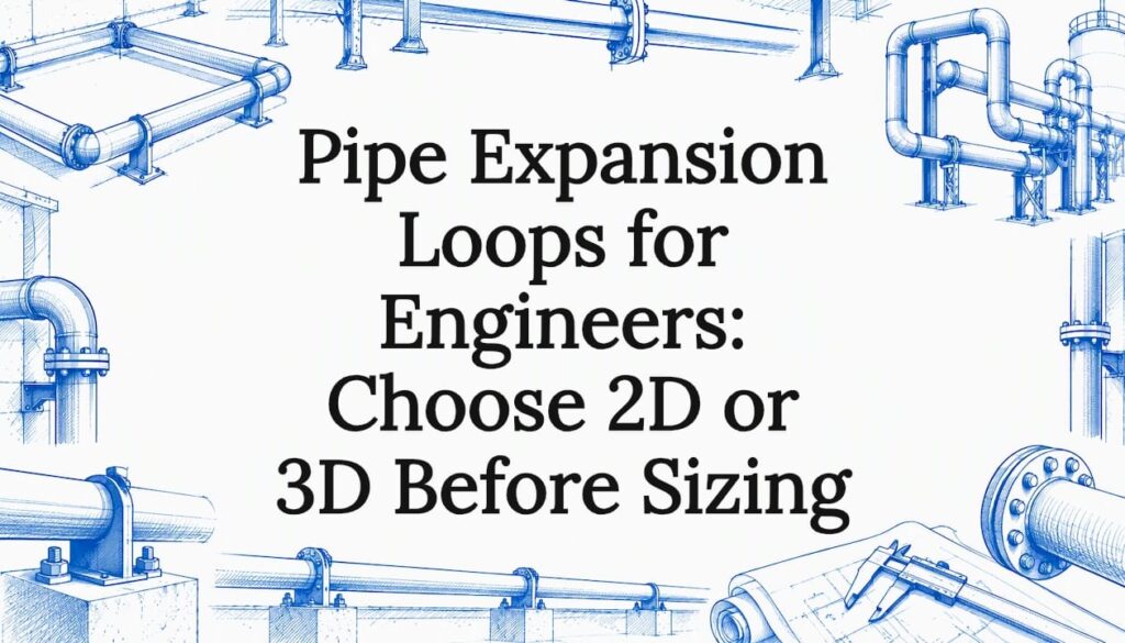
A pipe expansion loop is a U-shaped offset that turns axial thermal growth into controlled lateral deflection, and it is the right choice when you have the space, want a maintenance-light line with no bellows pressure thrust, and can keep equipment nozzle loads within limits. Size it from ΔL = α × L × ΔT and verify it under ASME B31.3 flexibility rules.
TL;DR:
- Calculate free movement for each anchored run with ΔL = α × L × ΔT, using the pipe manufacturer’s expansion coefficient and the coldest installation temperature.
- A 100 foot carbon steel line heated by 130°F grows about 1 inch; plastic pipe can expand up to ten times as much.
- Model anchors, approach guides, free loop legs, insulation clearance, spring forces, support loads, and equipment nozzle loads together; restraints inside flexible legs raise stress.
- Confirm bend radii with the fabricator, then validate leg lengths and stress under ASME B31.3; optimize oversized layouts only after formal analysis.
- After changes to operating temperature, flow, or supported weight, rerun flexibility analysis and check whether guides bind or measured movement differs from calculated growth.
Table of Contents
- How much will your pipe grow, and why does it matter?
- How do you size an expansion loop?
- Where do anchors and guides go?
- What does ASME B31.3 require, and what are the trade-offs?
- What checklist should go into your spec?
- How do material and pressure change your loop design?
- What fabrication and welding practices suit expansion loops?
- How should you inspect and maintain loops?
- Do expansion loops suit PV piping and energy storage containers?
- What I have learned about loop layouts
- Need engineered supports and piping from us?
- FAQ
- Sources
How much will your pipe grow, and why does it matter?
Every loop starts with one number: the free thermal growth between anchors. The governing relation is ΔL = α × L × ΔT, where α is the coefficient of thermal expansion, L is the straight run between anchors, and ΔT is the difference between installation and operating temperature. Standard physics treatments give the same formula, and the practical instruction for designers is to take α from the pipe manufacturer rather than from a generic table.
A 100-foot carbon steel pipe heated by 130°F grows roughly 1 inch, and plastic pipe can expand up to ten times that amount under identical conditions (source). That ratio is why plastic lines usually need offsets or loops long before steel lines of the same length do.
Three inputs drive the result:
- Material: α differs widely between carbon steel, stainless steel and plastics, so changing the spec changes the loop.
- Installation temperature: a line pulled tight on a cold morning grows more than one installed in summer heat.
- Operating ΔT: the hottest or coldest credible operating case, including steam-out or upset conditions, sets the design movement.
Long hot lines can grow tens of millimeters, which is why a thermal expansion table such as SimuPipe’s lists natural flexibility, loops, joints and snaking as the four standard strategies. Check natural flexibility first. Add a loop only when the routing fails the stress check.
How do you size an expansion loop?
Loop capacity comes from geometry. A longer leg is more flexible, so the lateral deflection a loop can absorb grows with the length of its legs. The required leg length follows from the ΔL you calculated, the pipe diameter and the allowable stress range. Start with a rule-of-thumb estimate, then confirm the numbers with analysis.
- Calculate ΔL for each run between anchors using the formula above.
- Pick the loop type. A 2D loop sits in one plane and suits a straight rack. A 3D loop adds a vertical offset when horizontal space is tight or when you must clear other lines.
- Estimate leg lengths from a handbook chart or the offset tables in TR-21, which also recommends minimum offset lengths for plastics.
- Check bend radii and segment lengths so the elbows can be fabricated and the straight pieces between them are not too short.
- Run the model. Verify the result in CAESAR II or AutoPIPE, which is the usual workflow when a routing fails static stress checks and a loop is added.
Symmetrical U-loops are the default, but multiple parallel lines on a shared rack often force nested or non-symmetrical loops. Analysis of non-symmetrical vertical loops indicates they remain effective under ASME B31.3 when the varying leg lengths are modeled properly.
Oversizing is the common mistake. Published optimization work using ASME B31.3 and CAESAR II found that loop dimensions and loop counts can often be reduced without compromising safety, once a formal analysis validates the design.
Pro Tip: Bend radius limits come from the fabricator’s tooling, not only from the code. A practical minimum bend radius guide helps you confirm that the elbows in your sketch can be built.
Where do anchors and guides go?
Anchors define where movement starts and stops. Guides keep the pipe moving along its intended axis so the loop deflects sideways instead of buckling. Without both, the calculated ΔL does not behave the way your model assumed.
Layout rules that hold up in the field:
- Anchor between loops: each straight run needs a fixed point at each end so growth is directed into the loop rather than into equipment.
- Guide the legs approaching the loop: place guides on the straight pipe adjacent to the loop to prevent lateral buckling, spaced per the code guidance and your analysis.
- Keep the loop’s own legs free: a guide or restraint inside the flexible portion defeats the purpose and raises stresses.
- Respect equipment: keep loops away from pump and vessel nozzles where possible, because the spring force of the loop acts on the nozzle.
- Account for insulation: insulated lines need clearance for the loop to move, and the added weight changes support loads.
A loop avoids the pressure thrust that a bellows creates, but it is not free of forces. Practical guidance on loops versus joints stresses assessing thermal spring forces, weight loads, nozzle loads and support interactions together, as one coordinated connection and support concept rather than treating the loop in isolation.
Support hardware matters as much as geometry. For cooling lines in particular, our data center pipe supports guide covers the failure modes to design out when brackets must carry a moving loop.
What does ASME B31.3 require, and what are the trade-offs?
ASME B31.3 covers materials, components, design, fabrication and inspection for process piping, and the 2024 edition lists changes that touch flexibility and stress intensification factors. The core requirement is that the designer keeps the stress from displacement within an allowable range. One worked explanation describes keeping total longitudinal stress within the allowable stress range using the code’s Equation (11).
ASME B31.3 requires a flexibility analysis so that piping components, especially at equipment connections, are not subjected to excessive forces that could lead to fatigue failure (source). That sentence is the practical reason a loop sketch is never enough on its own.
The ASHRAE pipe design chapter adds a useful frame for non-process systems: consider internal pressure stress, longitudinal stress from pressure and weight, and stress from expansion and contraction together.
Loops against joints comes down to a handful of trade-offs:
- Space and material: loops need rack width and extra pipe, joints do not.
- Maintenance: a loop has no moving parts to wear or leak.
- Flow resistance: extra bends add pressure drop, which matters on pumped cooling lines.
- Support complexity: loops add weight and guide points that need structural coordination.
- Pressure thrust: joints need heavy anchors to resist it, loops do not.
Where a first-pass design looks oversized, run an optimization pass with software before committing material.
What checklist should go into your spec?
Copy these into drawing notes or an RFQ:
- Calculate ΔL = α × L × ΔT for each anchored run, with α confirmed by the manufacturer.
- Choose a 2D or 3D loop and estimate leg lengths.
- Confirm bend radii and minimum segment lengths with the fabricator.
- Place anchors and guides, then check nozzle and support loads in CAESAR II or AutoPIPE.
- Record installation temperature and allowed movement in the procurement documents.
Pro Tip: State the installation temperature range on the drawing. A loop sized for a warmer installation can be undersized if the pipe is closed up at a colder temperature.
How do material and pressure change your loop design?
Material choice sets how big the loop must be and how hard it works. Carbon steel grows modestly and tolerates a wide stress range, so loops tend to be compact. Stainless steel has a higher expansion coefficient and lower thermal conductivity, which means longer legs for the same ΔT and, in insulated service, more uniform wall temperatures. Plastics expand far more, so loops or snaking are common, and their strength falls as temperature rises, which shrinks the allowable stress range exactly when you need it most.
Temperature and pressure interact. Hot, high-pressure service raises sustained stress from pressure and weight, leaving less margin for displacement stress under the allowable range. That is why the code treats sustained and expansion cases separately, and why you should check both. Cold service adds its own concerns: contraction pulls the loop the other way, and some materials lose toughness at low temperatures.
Practical selection points:
- Match the loop material to the line. Mixing materials introduces differential growth at transitions.
- Check the allowable stress at operating temperature, not at room temperature. Allowable values drop as metal temperature climbs.
- Consider corrosion allowance. Thinner remaining wall raises stress in the bends, where thinning is most likely.
- Plan for fatigue. Lines that cycle daily accumulate more stress cycles than lines that cycle yearly, and the stress range reduction for cycles should be applied.
- Use the manufacturer’s data for plastics, including temperature derating, as TR-21 directs for expansion and contraction in plastic systems.
If cycles, pressure or temperature push the design toward the edge of the allowable range, a longer or larger-radius loop is cheaper than a repeat failure.
What fabrication and welding practices suit expansion loops?
A loop is mostly elbows and short straights, so fabrication quality shows up in the bends. Choose between factory elbows and cold-bent pipe early. Factory long-radius elbows give predictable geometry and known stress intensification factors, while field bending suits larger radii but needs controlled wall thinning and ovality limits checked against the code and the shop’s tooling.
Welding concerns follow from the geometry:
- Weld count: every added weld is an inspection point and a distortion source. Fewer, better-placed welds beat many short spools.
- Weld location: keep girth welds out of the highest-stress zones at the bend tangents where practical.
- Fit-up: loops are dimensionally sensitive, so a few millimeters of misalignment on each leg adds up across the span. Use controlled fit-up and check overall dimensions before final welding.
- Distortion control: sequence welds symmetrically so the finished loop sits true. Our distortion control guidance explains how sequencing keeps fabricated assemblies in tolerance.
- Preheat and post-weld heat treatment: follow the procedure the material and thickness require under the code.
- Prefabrication: shop-built loop spools welded under controlled conditions usually beat field assembly, then ship with temporary braces that are removed after installation.
Coatings belong in the plan too. Loops on outdoor racks or in corrosive plants need surface preparation and coating before they go out, and abrasive-blast and coating specialists such as Professional Powder Coating handle large, heavy components of this kind. Coordinate coating limits near weld ends so you do not coat areas that still need inspection.
How should you inspect and maintain loops?
A loop has no wearing parts, but it still needs attention because it can be a highly stressed region of the line. Build inspection into commissioning and then into routine rounds.
At startup, walk the line through its first thermal cycle. Confirm that the loop moves in the direction and by the amount you calculated, that guides are not binding and that no neighboring pipe, cable tray or insulation is in the way. Mark reference positions on the supports so later movement is easy to read.
During operation, check these items on a schedule:
- Support condition: look for jammed guides, displaced shoes, bottomed-out spring hangers and loose hardware.
- Insulation and coatings: damaged insulation lets water in, and corrosion under insulation can hide at the bends. Our corrosion under insulation inspection and spec guidance lays out what to look for.
- Bends and welds: examine elbows and girth welds for cracking, distortion and wall loss using the methods your inspection plan specifies.
- Alignment: check that the loop sits in its original plane and that legs have not sagged.
- Movement records: compare observed growth against calculated ΔL. A large mismatch signals a stuck guide, a changed operating temperature or a design assumption that no longer holds.
After any change in operating temperature, flow regime or supported weight, revisit the flexibility analysis. A loop sized for one duty is not automatically fit for another. Document findings so trends are visible across shutdowns rather than rediscovered each time.
Do expansion loops suit PV piping and energy storage containers?
Loops work in these settings, but the layout limits are tighter than on a process rack. Photovoltaic plants use piping for water and fire protection, and containerized battery systems use liquid cooling loops that run inside confined enclosures. Temperature swings from sun exposure and from battery duty cycles are the cause of movement, and the daily cycling makes fatigue a real consideration.

Inside a container, floor and wall space for a full U-loop is often not available. That pushes designers toward compact 3D loops, flexible hose sections or deliberate routing changes that provide natural flexibility. Outdoors, long headers across solar fields are better candidates for classic loops, with guides on the approaches to keep the pipe aligned across terrain and thermal swings.
Coordination points to settle early:
- Thermal management interface: movement at cooling manifolds must stay within what connected equipment tolerates. Our BESS thermal management resource covers the thermal design side of these systems.
- Container structure: supports must attach to structure that can carry the loop’s reaction loads without local distortion.
- Transport and shipping: a mobile or prefabricated container is lifted and trucked, so loops and their supports must survive vibration and handling, with any temporary restraints clearly tagged for removal.
- Mounting systems: where piping runs along solar structures, the supporting frame must allow for the pipe’s movement. Our PV mounting system range and energy storage container range are the engineered platforms we supply for these installations.
Treat the piping, supports and enclosure as one design problem. A loop that passes stress analysis but has no physical room to deflect fails in the field.
What I have learned about loop layouts
In my notes from coordinating piping with structural and insulation teams, the same pitfalls repeat. The loop gets drawn before the rack is final, a beam or cable tray lands in its swing path, and insulation thickness is added late and eats the clearance. Settle the envelope with the structural team first, then analyze. Our engineering team works on exactly these coordination problems, and you can reach out for project-level support or complex loop optimization.
— Hu
Need engineered supports and piping from us?
We supply engineered options for the piping and support side of loop designs, so you can source components from one place:
- Annular pipe products and data center cooling piping: stainless steel cooling piping for demanding facilities.
- GQ-FL series flexible support: a flexible support option for systems with thermal movement.
- OEM and ODM project solutions: custom engineering for project-specific requirements.
For a quote, send us your system drawings, the operating and installation temperatures, the allowed movement and your expected support stiffness. Start from our products overview and tell us what the line has to do.
FAQ
What is the formula for thermal expansion?
The formula is ΔL = α × L × ΔT, where α is the expansion coefficient, L is the original length and ΔT is the temperature change. Get α from the pipe manufacturer for your exact material, as standard physics references also note.
Does PVC pipe expand?
Yes. Plastic pipe expands far more than metal, and TR-21 guidance on plastics piping provides offset and loop calculations along with minimum offset lengths to handle it.
What are the different types of pipe expansion joints and alternatives?
The usual strategies are natural flexibility, expansion loops, expansion joints such as bellows, and snaking for plastics, as listed by SimuPipe. Loops avoid bellows pressure thrust but need space and a coordinated support concept.
When should you use a loop instead of a joint?
Use a loop when space allows and you want a line with no moving parts. Practical guidance says to check natural flexibility first and still assess spring forces and nozzle loads.