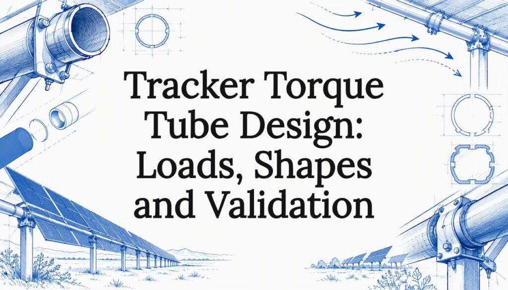
A tracker torque tube is designed around three jobs: carry the modules in bending between piles, transmit drive torque along the row, and survive wind-induced torsion without twisting out of alignment or entering aeroelastic instability. Get the section, wall thickness, span, connections, coating and stow strategy right together, and the row tracks accurately for decades. Get one wrong and the others cannot compensate.
This guide is for engineers, EPC project managers and procurement teams who need to specify or review a torque tube. It covers what the tube does, the loads that govern, how cross-section shapes compare, material and corrosion choices, and how designs are analyzed and tested.
TL;DR
- The torque tube is the backbone of a single-axis tracker: it holds the modules, rotates with the drive, and passes wind torsion to the drive and locks.
- Design for bending between piles and for torsion that accumulates along the row, then check dynamic behavior, not just static strength.
- Closed sections resist twisting far better than open ones. Round sections are the most efficient in pure torsion, while square and other shapes trade some of that for connection and module-mounting convenience.
- Flat stow is the most prone to torsional instability, so stow angle is a structural decision that should come from wind-tunnel evidence.
- Validate with finite element analysis and wind-tunnel data under the standards your jurisdiction requires.
Table of Contents
- What a torque tube does in a single-axis tracker
- The loads that govern the design
- How the torque tube hands loads to drives and locks
- Comparing tube shapes
- Material, dimensions and corrosion protection
- Analysis and validation
- Our perspective
- Working with a manufacturer on your tracker
- FAQ
- Sources
What a torque tube does in a single-axis tracker
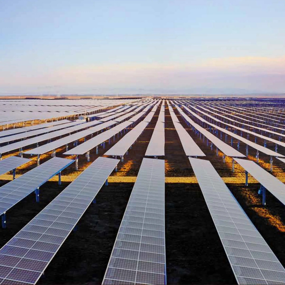
In a horizontal single-axis tracker, the torque tube supports the PV modules and is turned by one or more motors, often through slew drives, so that every module in the section follows the sun together (TaiyangNews). A published US patent describes a slew drive rotating the torque tube around its longitudinal axis, which is the basic arrangement most designers start from.
That makes the tube more than a beam. It is a primary backbone: it carries the modules, rotates the assembly and passes wind-induced torsional loads to the drive or locking mechanism. Three consequences follow for design:
- Strength and stiffness both matter. A tube can be strong enough not to yield and still be too flexible to hold module angle along a long row.
- Alignment is a performance issue. Trackers are usually simulated as though every module on a section sits at one orientation. Research on torque tube twisting challenges that assumption, because real tubes twist along their length, so twist in the tube shows up as energy loss as well as structural risk.
- The tube interacts with everything it touches. Bearings, drive, dampers, module clamps and piles all share the loads, so a tube specification is really a system specification.
If you are still weighing whether a tracker is the right architecture for your site, our guide to solar tracking systems and the comparison of tracker versus fixed tilt yield and LCOE cover that decision before the torque tube enters the picture.
The loads that govern the design
Bending between piles
The tube must resist bending from module weight and wind pressure between support piles (Heaven Designs). Pile spacing is the main lever here. Longer spans reduce the number of foundations, which is attractive for cost, but they raise bending moment and deflection in the tube. This is why tube design and foundation planning cannot be separated. Our note on cutting foundation count on utility-scale racking explains the project-level side of that trade.
Torsion that accumulates along the row
Wind pressure acts off the axis of rotation, so it produces a twisting moment. That torsion accumulates along the row toward wherever the drive or lock holds the tube. The section nearest the drive carries the most torque, and the far end twists the most. For a drive placed mid-row, both halves behave like cantilevers of torque. Where you place the drive, and how many you use, changes the required tube torsional stiffness.
Dynamic wind: gusts and torsional galloping
Static design wind loads are not enough for a flexible, slender structure. Dynamic gust loads can induce torsional galloping, a violent twisting motion that can escalate quickly and lead to structural failure. Researchers at the University of Oviedo note that the push toward very slender trackers for cost optimization has made aeroelastic instability a design issue that has to be understood to prevent catastrophic failures.
Two points matter in practice:
- Tilt angle changes the threshold. In wind-tunnel tests on one tracker, the critical velocity for torsional galloping depended on tilt angle, and near-horizontal angles showed higher critical velocities in that particular tracker (University of Oviedo). That is a result for a specific geometry, not a universal rule, which is why each tracker needs its own testing.
- Stiffness and span both drive the response. CPP Wind’s work on low-tilt behavior points to torque tube torsional stiffness and flexible span length as factors in deflection and fluid-structure interaction.
Fatigue and load cycling
A tube rotates through its full range every day and sees fluctuating wind for years. Connections, drive interfaces and bearing housings are where fatigue tends to show first, so detail design matters as much as the tube’s nominal section. Field data supports the need for care: a full-scale measurement study over 109 days on a one-in-portrait tracker in South Africa found that both torsional and bending modes of the torque tube contributed to load effects, and that high wind events did not necessarily arrive from the dominant wind direction.
Stow strategy
Stow angle is a structural decision, not a controls setting. Research indicates that flat stow is the most prone to torsional instability, and the right angle should come from the supplier’s wind-tunnel testing. CPP Wind researchers also recommend that isolated trackers and those on the periphery of an array avoid flat tilt angles during high-wind events. Edge rows are exposed to the least shielding, so they deserve the most conservative treatment.
How the torque tube hands loads to drives and locks
The tube is the load path between the wind and the mechanical parts that hold it. Everything that twists the tube ends up in a drive, a lock or a damper. That shapes the design in a few ways:
- The drive interface needs a connection that carries torque without slip or local yielding of the tube wall.
- Bearings must allow rotation while resisting lateral wind load and the self-weight reaction at each pile.
- Any intermediate locking or damping point reduces the effective torsional span, which can let you lower the tube section but adds parts to maintain.
For teams comparing drive and anchoring hardware on the equipment side, a marketplace for auger and anchor drives shows what installation equipment is available to drive the piles the tube will eventually sit on.
Comparing tube shapes
Tracker torque tubes come in round, square, pentagonal, octagonal and D-shaped sections, and are commonly galvanized (PandaPipe). Instead of ranking shapes in the abstract, compare them on what the governing load demands.
| Criterion | Round | Square / rectangular | Octagonal | D-shaped / other |
|---|---|---|---|---|
| Torsional efficiency | Highest for a closed section | Good, lower than round | Between round and square | Depends on proportions |
| Bending behavior | Same in every direction | Same in every direction for square | Near-uniform | Directional |
| Module and clamp attachment | Needs curved-surface hardware | Flat faces simplify clamps | Flat faces with a rounder profile | Often built around a specific clamp |
| Connection to drive and bearings | Simple circular interface | Needs matched square couplings | Needs matched couplings | Typically proprietary |
The basis for the first two columns comes from structural design guidance. AISC states that closed tubes provide torsional stiffness and a high weak-axis moment of inertia, and that round and square tubes have the same moment of inertia about any axis. AISC Design Guide 9 adds that closed sections generally resist torsion better than open ones, with circular hollow sections the most efficient for torsional loading, and square and rectangular hollow sections also outperforming open W-shapes and channels.
The practical reading: a closed section is a given for a torque tube, because open sections give up torsional stiffness. Between closed shapes, pick the one that gives you the stiffness you need at the lowest steel weight while keeping module clamps, couplings and fabrication simple. Shape alone rarely decides the project. Wall thickness, span and drive placement usually have a larger effect than moving from one closed shape to another.
Material, dimensions and corrosion protection
Steel and wall thickness
The torque tube must support heavy, dynamic loads, and galvanized steel is the typical choice (TaiyangNews). Within that, three decisions interact:
- Yield strength. Higher-strength steel permits a thinner wall for the same bending capacity, but torsional stiffness depends on geometry and the shear modulus, which does not rise with strength. A thinner high-strength tube can pass a strength check and still be too flexible. Always check twist and deflection separately.
- Wall thickness and diameter. For a closed section, increasing diameter raises torsional and bending stiffness far more efficiently than adding wall, but a larger tube means larger bearings and couplings.
- Span. The span between piles sets bending demand; the length between drive and row end sets torsion demand.
Coating
Galvanizing protects the tube across a design life measured in decades, so the coating spec belongs in the same document as the structural spec. Define the coating standard, the minimum thickness, and what happens at cut ends, weld zones and drilled holes, because that is where protection is interrupted. Soil and atmospheric corrosivity at the site should set the requirement, not a default. Fabrication quality control matters here: our guide to steel fabrication quality control describes a three-phase approach to checking material, process and finished parts.
Connections
A tube row is a chain of segments, and the splice and the drive coupling are common weak points. Design them for the full torque they pass, check bearing and bolt-hole stress in the tube wall, and treat the connection as a fatigue detail. For fabrication questions such as forming and cutting tubular sections, a tube bending and fabrication resource gives background on how metal tubing is shaped, which is useful when you consider how tolerances affect fit-up.
Analysis and validation
Finite element analysis
Structural analysis of a tracker typically uses the finite element method, with dead and wind loads applied under the governing standard or a wind-tunnel study. One public tracker specification from India, for example, calls for finite-element analysis alongside site-based wind design and wind-tunnel-supported stow and aeroelastic analysis. FEA is where you check combined bending and torsion, local stress at connections, and the buckling of thin walls near concentrated loads.
Wind-tunnel testing
Static code coefficients do not capture aeroelastic behavior. Wind tunnel tests give the critical velocity thresholds for aeroelastic events, which feed the choice of stow angles and the structural stiffness you need. In the US, FM’s ground-mounted PV data sheet points to wind tunnel testing under ASCE 7-22 and ASCE 49-21 to obtain lift, drag and moment coefficients for trackers, because the arrangement of neighboring units alters loads on the rest.
Field measurements add another check. The South African study mentioned earlier reported lower combined wind load coefficients than design codes, which suggests code values can be conservative for some configurations, though that is one tracker at one site and is no basis for cutting margins (ScienceDirect).
Standards depend on jurisdiction
Load assumptions are set locally. In the US, ASCE 7 wind provisions are the usual reference. Other countries use their own codes, such as IS 875 in India. If a project is financed or insured across borders, agree early which code and which wind speed return period govern. For help navigating how calculation standards and compliance are described in a different regulatory context, a general guide to solar calculations shows how such requirements are framed, though a US project should always be checked against the local building authority and a licensed structural engineer.
A review checklist
- State the design code, wind speed, exposure and risk category.
- Confirm pile spacing, tube section, wall thickness and steel grade together.
- Check bending, torsion and combined stress, then check twist and deflection against alignment limits.
- Locate the drive and locks, and compute torque at every connection.
- Obtain wind-tunnel-based stow angles and critical velocities for the exact tracker geometry.
- Review edge and corner rows separately from interior rows.
- Specify coating, cut-end treatment and inspection.
- Define fabrication tolerances and test procedures for splices and couplings.
Our perspective
We make steel for a living, and that shapes how we think about a torque tube: it is a steel fabrication problem as much as a structural one. A design that looks right on paper only holds if every tube leaves the factory with the same wall, the same straightness and the same coating as the one before it.
That is why we put weight on integrated, large-scale manufacturing and strict quality control in-house. Consistency across thousands of tubes along thousands of rows is what keeps alignment and load paths behaving as the engineer modeled them.
We also believe the torque tube should be specified with the project, not pulled from a catalog. Wind exposure, soil, row length and drive layout differ from site to site, and engineered solutions for demanding real-world applications are what we are built to supply. Our OEM and ODM capability and project-specific engineering exist so that the tube, the piles and the tracker work as one system.
Guoqiang has been manufacturing since 1998 and has contributed to more than 3,000 photovoltaic projects worldwide, so we bring that experience into every conversation about tube design.
Hu
Working with a manufacturer on your tracker
If you are specifying tracker structure for a utility-scale project, we supply the GQ-T Chaoyang Series Tracker System, foundation products such as the photovoltaic pile tube and nail series, and OEM and ODM mounting solutions with project-specific engineering through our PV mounting system range. Send us your site loads, row layout and code requirements, and our engineers can work through the structure with you.

For early budgeting, our tracker cost guide explains what drives price. To discuss a project, start from the Gq-international site.
FAQ
What is the best torque tube shape for a solar tracker?
There is no single best shape. Closed sections are essential for torsional stiffness, and round tubes are the most efficient in torsion, per AISC guidance. Square and other shapes can ease module clamping and couplings. Choose based on required stiffness, steel weight, connection design and tracker architecture.
Why does torsion matter more than bending in a long tracker row?
Wind pressure acts off the axis of rotation, and the resulting twist accumulates along the row toward the drive. A tube can pass a bending check but still twist enough to misalign modules or approach instability. Torsional stiffness and drive placement therefore need their own checks.
How is stow angle chosen?
Stow angle is a structural decision based on wind-tunnel testing of the specific tracker. Research shows flat stow is the most prone to torsional instability, and peripheral or isolated trackers especially should avoid flat tilt in high wind. The supplier’s test data should set the angle.
What coating do torque tubes need?
Galvanized steel is the typical choice for torque tubes. The exact standard and coating thickness should reflect site corrosivity and design life, and the specification should cover cut ends, welds and drilled holes where the coating is interrupted.
Sources
- The Basics Of HSAT Systems, TaiyangNews
- US11165385B2, Distributed torque single axis solar tracker
- Solar Tracker Torque Tube Design: Torsion, Twist and Piles
- Experimental determination of the resistance of a single-axis solar tracker to torsional galloping
- Solar Tracker Wind Load Design: Torque Tubes & Bearings
- Low-Tilt Torsional Instability of Single-Axis Solar Trackers
- Torsional Instability of Single-Axis Solar Tracking Systems
- Field measurements of wind load effects in a photovoltaic single-axis tracker mounting rail
- Designing With Structural Tubing, AISC
- Torsional Analysis of Structural Steel Members, AISC Design Guide 9
- Tracker specification with FEA and wind design requirements
- FM Data Sheet 7-106, Ground-Mounted Solar Photovoltaic Power